Panasonic AJ-PX800GF Basic Operating Instructions - Page 96
Supplying the time code externally
 |
View all Panasonic AJ-PX800GF manuals
Add to My Manuals
Save this manual to your list of manuals |
Page 96 highlights
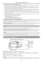
Chapter 4 Shooting - Setting the time data 5 Input a reference time code and reference video signal that are in a phase relationship (that conforms to time code specifications) to the terminal and the terminal. The built-in time code generator is locked to the reference time code. When approximately ten seconds has elapsed after locking, the external lock status will be held even if the reference time code from the external device is disconnected. ffWhen the input reference signal of genlock is disrupted, recording cannot be performed normally. [TEMPORARY PAUSE IRREGULAR SIG] is displayed in the viewfinder, and the clip is divided. The continuity of the time code is not guaranteed. Recording will be resumed when the signal returns to normal. However, during loop recording, recording does not resume. ffWhen external lock is performed, the time code is instantaneously locked to the external time code, the same value as the value of the external time code is output to the counter display area, and the [TCG[R]] display is black and white inverted. Do not set to the recording mode for several seconds until the sync generator has stabilized. Also, lock the time code to the terminal signal. ffWhen using the camera with [ON] set in the main menu → [RECORDING SETUP] → [PRE REC], disrupted images or stopped time codes may be recorded if the time code is switched from recording run to free run immediately before recording or an external time code is input to be slavelocked to the terminal. ffIf you execute the slave once, even if there is no longer terminal and terminal input, the slave status is maintained. However, in the following cases, the slave status will be released. - When time code is set on the [SET01:TC/UB] screen of SmartUI - When the power is turned off - When switching between [DF]/[NDF] in [DF MODE] - When [TC_MD] is set to [R‑RUN] on the [SET01:TC/UB] screen of SmartUI - When switching between [REC FORMAT] and [CAMERA MODE] Setting of user bits when the time code is externally locked To lock user bits to the input values from an external source, set the main menu → [RECORDING SETUP] → [UBG MODE] to [EXT]. Regardless of the setting of recording run/free run, it is slaved to user bits values input to the terminal. Canceling the external lock After stopping supply of the external time code, set the main menu → [RECORDING SETUP] → [UBG MODE] to other than [EXT]. Cautions when switching the power supply from the battery to the external DC power supply while an external lock is active To keep on the time code generator power supply continuously, connect an external DC power supply to the terminal and then remove the battery pack. If the battery pack is removed first, there is no guarantee that the time code will stay externally locked. External synchronization of the camera unit while an external lock is active While an external lock is active, the genlock is activated on the camera unit by the reference video signal input to the terminal. @@NOTE tt To externally lock multiple units with the camera as the master device, set to the same setting as on the camera. Note that in a system using a mixture of interlaced and progressive scanning, the continuity of the video and time codes is not guaranteed. tt When externally locking in 24PN Native mode, be sure to input non-drop frame time codes. An external lock is not possible using drop frames. Also, images may be disrupted the instant that the external lock is activated, though this is due to alignment of the 5-frame cycle and is not a malfunction. Supplying the time code externally You can supply the output time codes to a VTR or other recording device from the camera by matching the camera images or the replayed images. terminal or terminal VIDEO IN terminal SDI IN terminal HD SDI IN terminal VTR, etc. TC IN terminal terminal 1 Set [MON OUT] in the main menu → [IN/OUT SEL] → [TC OUTPUT REF]. 2 Set [HD SDI] or [COMPOSITE] in the main menu → [OTHER FUNCTIONS] → [GL PHASE] to match the supplied video output. 3 Set [TCG/TCR] in the main menu → [IN/OUT SEL] → [TC OUT]. 4 Set [TC OUT] in the main menu → [IN/OUT SEL] → [TC IN/OUT SEL]. @@NOTE tt If you set [TC OUTPUT REF] to [MON OUT] in the main menu → [IN/OUT SEL], the input time code will be output to match the video output delay. - 96 -
-
 1
1 -
2
-
3
-
4
-
5
-
6
-
7
-
8
-
9
-
10
-
11
-
12
-
13
-
14
-
15
-
16
-
17
-
18
-
19
-
20
-
21
-
22
-
23
-
24
-
25
-
26
-
27
-
28
-
29
-
30
-
31
-
32
-
33
-
34
-
35
-
36
-
37
-
38
-
39
-
40
-
41
-
42
-
43
-
44
-
45
-
46
-
47
-
48
-
49
-
50
-
51
-
52
-
53
-
54
-
55
-
56
-
57
-
58
-
59
-
60
-
61
-
62
-
63
-
64
-
65
-
66
-
67
-
68
-
69
-
70
-
71
-
72
-
73
-
74
-
75
-
76
-
77
-
78
-
79
-
80
-
81
-
82
-
83
-
84
-
85
-
86
-
87
-
88
-
89
-
90
-
 91
91 -
 92
92 -
 93
93 -
 94
94 -
 95
95 -
 96
96 -
 97
97 -
 98
98 -
 99
99 -
 100
100 -
 101
101 -
102
-
103
-
104
-
105
-
106
-
107
-
108
-
109
-
110
-
111
-
112
-
113
-
114
-
115
-
116
-
117
-
118
-
119
-
120
-
121
-
122
-
123
-
124
-
125
-
126
-
127
-
128
-
129
-
130
-
131
-
132
-
133
-
134
-
135
-
136
-
137
-
138
-
139
-
140
-
141
-
142
-
143
-
144
-
145
-
146
-
147
-
148
-
149
-
150
-
151
-
152
-
153
-
154
-
155
-
156
-
157
-
158
-
159
-
160
-
161
-
162
-
163
-
164
-
165
-
166
-
167
-
168
-
169
-
170
-
171
-
172
-
173
-
174
-
175
-
176
-
177
-
178
-
179
-
180
-
181
-
182
-
183
-
184
-
185
-
186
-
187
-
188
-
189
-
190
-
191
-
192
-
193
-
194
-
195
-
196
-
197
-
198
-
199
-
200
-
201
-
202
-
203
-
204
-
205
-
206
-
207
-
208
-
209
-
210
-
211
-
212
-
213
-
214
-
215
-
216
-
217
-
218
-
219
-
220
 |
 |
