Netgear WC7520-Wireless Reference Manual - Page 68
The Add DHCP Server pop-up window displays, Table 11., DHCP settings
 |
View all Netgear WC7520-Wireless manuals
Add to My Manuals
Save this manual to your list of manuals |
Page 68 highlights
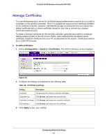
ProSafe 20-AP Wireless Controller WC7520 Figure 30. The DHCP Server List shows the DHCP servers that are already configured on the wireless controller. 2. Click Add. The Add DHCP Server pop-up window displays: Figure 31. 3. Configure the settings as explained in the following table: Table 11. DHCP settings Setting Enabled Use VLAN Interface VLAN IP Network Description Select this check box to enable the DHCP server. When the check box is cleared, the DHCP server is disabled. Select this check box to allow the DHCP server to function with multiple VLANs. Enter the DHCP server VLAN ID. The range is between 1 and 4094. The DHCP server will service this VLAN. Enter the IP address for the wireless controller in the VLAN that you have specified in the VLAN field. If you have not selected the Use VLAN Interface check box, the IP address of the wireless controller's management VLAN is used. Configuring Network Settings 68
-
 1
1 -
2
-
3
-
4
-
5
-
6
-
7
-
8
-
9
-
10
-
11
-
12
-
13
-
14
-
15
-
16
-
17
-
18
-
19
-
20
-
21
-
22
-
23
-
24
-
25
-
26
-
27
-
28
-
29
-
30
-
31
-
32
-
33
-
34
-
35
-
36
-
37
-
38
-
39
-
40
-
41
-
42
-
43
-
44
-
45
-
46
-
47
-
48
-
49
-
50
-
51
-
52
-
53
-
54
-
55
-
56
-
57
-
58
-
59
-
60
-
61
-
62
-
 63
63 -
 64
64 -
 65
65 -
 66
66 -
 67
67 -
 68
68 -
 69
69 -
 70
70 -
 71
71 -
 72
72 -
 73
73 -
74
-
75
-
76
-
77
-
78
-
79
-
80
-
81
-
82
-
83
-
84
-
85
-
86
-
87
-
88
-
89
-
90
-
91
-
92
-
93
-
94
-
95
-
96
-
97
-
98
-
99
-
100
-
101
-
102
-
103
-
104
-
105
-
106
-
107
-
108
-
109
-
110
-
111
-
112
-
113
-
114
-
115
-
116
-
117
-
118
-
119
-
120
-
121
-
122
-
123
-
124
-
125
-
126
-
127
-
128
-
129
-
130
-
131
-
132
-
133
-
134
-
135
-
136
-
137
-
138
-
139
-
140
-
141
-
142
-
143
-
144
-
145
-
146
-
147
-
148
-
149
-
150
-
151
-
152
-
153
-
154
-
155
-
156
-
157
-
158
-
159
-
160
-
161
-
162
-
163
-
164
-
165
-
166
-
167
-
168
-
169
-
170
-
171
-
172
-
173
-
174
-
175
-
176
-
177
-
178
-
179
-
180
-
181
-
182
-
183
-
184
-
185
-
186
-
187
-
188
-
189
-
190
-
191
-
192
-
193
-
194
-
195
-
196
-
197
-
198
-
199
-
200
-
201
-
202
-
203
-
204
-
205
-
206
-
207
-
208
-
209
-
210
-
211
-
212
-
213
 |
 |
