LiftMaster MA Owners Manual - Page 9
Inputs J5 Terminal Strip, Inputs
 |
View all LiftMaster MA manuals
Add to My Manuals
Save this manual to your list of manuals |
Page 9 highlights
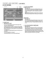
WIRING » INPUTS INPUTS (J5 TERMINAL STRIP) DO NOT connect ANY device which would deliver ANY voltage of ANY kind to these terminals. The J5 terminal strip is used for controlling the barrier arm with various accessories such as receivers, loop detectors, access controls, and push button stations. Use common and normally open contacts from devices connected to these inputs. The J5 terminal strip is located on the top of the control board. Make connections to the appropriate points for the desired operation. Wires should be UL approved 600 volt rated and at least 18 AWG. They are to be routed through the upper grommet in chassis to avoid chafing. All external control devices must have normally open dry contacts. TERMINAL 1,2,3 4 5 6 7 8 9,10,11,12 INPUT OPEN AUXILIARY OPEN SAFETY CLOSE BACK-AWAY (FREE EXIT) SHADOW (SAMS) COMMON EXPLANATION These inputs will trigger gate open when pulsed or hold gate open with maintained contact. When released gate will close if closing timer is on or if close input is given. Same as 1, 2 and 3 with S2 switch 6 off. With S2-6 DIP switch in the ON position, the Multiple Vehicle Memory will activate, with inputs on terminal 4 and Common (COM) on the J5 terminal strip. Use with laser scanners or card readers and (transmitters with timed anti-pass back). With S1 switch 5 on, this input becomes a momentary pulse open, pulse close. This input is generally not used with the MEGA ARM. If used its function is to make gate reverse and go back to the open position if it was closing. Input is disabled when gate is closed. When used with a vehicle detector, it is recommended that the presence contacts (N.O. & C.) be used for the close input. This input will close gate after input is applied and then removed. It will stop the open cycle and reverse gate to close. EXAMPLE: Car crosses over close loop before arm reaches full open position- gate will reverse and close. NOTE: The close input also acts as a safety-stop in that if gate is closing and a tailgater is sensed at the close input, the gate WILL STOP its closing motion and not continue to close until the close input is removed or gate is re-opened. This input is used as a free exit input to open gate. When input is active, gate will open and close immediately once input is removed. EXAMPLE: Car pulls up to exit loop, gate opens; car "backs-away" from exit loop and gate closes. Used to monitor an auxiliary open limit switch of another operator in the same lane. SAMS with memory feature, see page 19. These are the commons (0 Vdc) to be used to activate above inputs. NOTE: Above inputs are tied to LED indicators to show input command activity. J5 Wiring Inputs on the control board C18 U18 C15 F MANUAL 1 2 3 4 5 6 7 8 9 1Ø 11 12 OPEN Q2 J5 S3 T2 T4 T6 T8 T1 T3 T5 T7 CLOSE OPEN 1 OPEN 2 OPEN 3 R21 AUX 4 SAFETY 5 CLOSE 6 BACK 7 SHADOW 8 C16 D15 D16 D17 D18 D19 D22 D23 D24 3 R24 R35 R41 R46 R5Ø R61 9
-
 1
1 -
2
-
3
-
 4
4 -
 5
5 -
 6
6 -
 7
7 -
 8
8 -
 9
9 -
 10
10 -
 11
11 -
 12
12 -
 13
13 -
 14
14 -
15
-
16
-
17
-
18
-
19
-
20
-
21
-
22
-
23
-
24
 |
 |
