LiftMaster MA Owners Manual - Page 10
Accessory And Relay Connections + Battery Installation, Accessory And Relay Connections
 |
View all LiftMaster MA manuals
Add to My Manuals
Save this manual to your list of manuals |
Page 10 highlights
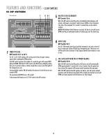
WIRING » ACCESSORY AND RELAY CONNECTIONS + BATTERY INSTALLATION ACCESSORY AND RELAY CONNECTIONS These terminals will provide battery backed power to 24 Vdc devices and are located at the bottom of the control board at J4 terminals 1 and 2. Terminal 1 is 24 Vdc (+) and number 2 is 0 Vdc (-). Peripheral CLASS 2 low voltage devices that require 24 Vdc power maybe connected here (500 ma. maximum). EXAMPLE: Vehicle detector, radio receiver. K1 D11 U19 Aux Relay J1 C NC NO DC 1 PWR D12 R13 J4 D14 BAT- 1 F3 MOV ACC+ ACC- BAT- BAT+ 24VAC XFM 24 Vdc (+) 0 Vdc (-) The K1 Relay (optional) and terminal strip (J1) are used for auxiliary devices such as Counters, Alarms,Buzzers, and SAMS (Sequence Access Management System). RELAY OUTPUT K1 - (OPTIONAL) S1-6 S1-8 OFF OFF ON OFF OFF ON ON ON RESULT Relay will fire (latch) when gate is not closed. Relay will fire when arm is pushed up off of limit switch (use with slip clutch option) and fires relay when a tail-gate is detected by the close loop ANTI TAIL-GATE ALARM. Relay will pulse relay when arm reaches full open position. Relay will only pulse when input is given to J5 1,2,3 inputs. (Refer to pages 14-15.) Relay Connection Terminals on the J4 Terminal Block S1 DIP Switch Block S1-6 S1-8 1 J2 AUX LIMITS D8 S1 12 R1 1 D1Ø S2 12 BATTERY INSTALLATION CONNECTING THE BATTERY LEADS - ALWAYS CONNECT AC POWER BEFORE INSTALLING BATTERIES. 1 Connect AC power BEFORE installing batteries. 2 Install two new, fully charged 12 volt DC batteries on shelf next to motor. 3 Connect red lead from the operator control board to the positive (RED +) terminal of one battery. 4 Connect the black lead from the operator control board to the (BLACK -) terminal of the OTHER battery. - 12 VDC Battery + - 12 VDC Battery + 5 Connect the jumper (provided) between the remaining terminals of each battery if one is not already in place. IMPORTANT: Do not run operator without installing the batteries. Replace batteries in pairs using LiftMaster MBAT or 29-NP712 batteries. Failure to install batteries correctly will cause damage and will not be covered by warranty. 10 Black Lead Jumper Red Lead
-
 1
1 -
2
-
3
-
4
-
 5
5 -
 6
6 -
 7
7 -
 8
8 -
 9
9 -
 10
10 -
 11
11 -
 12
12 -
 13
13 -
 14
14 -
 15
15 -
16
-
17
-
18
-
19
-
20
-
21
-
22
-
23
-
24
 |
 |
