LiftMaster MA Owners Manual - Page 13
Features And Functions » S1 Dip Switches
 |
View all LiftMaster MA manuals
Add to My Manuals
Save this manual to your list of manuals |
Page 13 highlights
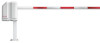
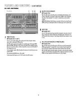
FEATURES AND FUNCTIONS » S1 DIP SWITCHES S1 DIP SWITCHES A S1 Dip Switch Block BC D E 1 1 J2 J AUX LIMITS M/S R D8 D1Ø S1 S2 1 2345678 1 2345678 R1 R12 U4 A FAST RUN TIMER (FULL SPEED RUN TIMER) DIP Switch S1-1 to S1-4 When the gate operator activates, it ramps up and slows down for a fixed amount of time, but will run at full speed for variable amounts of time depending upon the settings of the S1-1 to S1-4 DIP switches. Each DIP switch represents increments of 1/8 second. When DIP switches S1-1, S1-2 and S1-3 are in the ON position, the Fast Run Timer is set to 2-3/8 seconds by factory default. When DIP switches S1-1 to S1-4 are set in the OFF position, the full speed run time is 1-1/2 seconds. The longer the operator runs at full speed, the less ramp up and slow down time. When adjusting, make sure the Fast Run Timer settings DO NOT overrun the slow down time. B SINGLE BUTTON FUNCTION (INCLUDING PULSE RADIO RECEIVER OPEN/CLOSE) DIP Switch S1-5 With S1-5 DIP switch in the ON position, the Single Button Function (Command to Open/Command to Close) will activate, with inputs on terminal 4 and Common (COM) on the J5 terminal strip. Any of the terminals 9-12 on the J5 terminal strip can be used for common. When using this feature with the radio receiver (provided), move the radio wire from terminal 1 to terminal 4 on the J5 terminal strip. D HANDING THE BARRIER ARM DIP Switch S1-7 The J4 Motor Wiring is controlled by DIP switch S1-7. The Handing of the Barrier Arm may be changed from right-hand to left-hand operation by reversing the factory default motor connections. NOTE: Right-hand or left-hand operation is determined by facing the control board with the barrier arm in the CLOSED position. If the barrier arm is to the right, it is set for right-hand gate operation. 1. Disconnect power to the operator. 2. For left-hand operation reverse the motor wires on J4-7 (blue wire) and J4-8 (orange wire) (see below). D12 D14 F3 R13 U19 J4 BAT- MO MOTOR 1 ACC+ ACC- BAT- BAT+ 24VAC XFMR MOTOR Blue Orange 3. Set DIP switch S1-7 to the ON position. 4. Turn the motor pulley until the barrier arm is to the left. 5. Turn the Limit Cam so the Limit Cam is parallel to the arm and just behind the limit sensor. 6. Connect power to the operator. (Control Board) CAM POSITION E K1 RELAY (OPTIONAL) DIP Switch S1-8 Auxiliary devices such as Counters, Alarms, Buzzers, and SAMS (Sequence Access Management System), can be wired into the K1 Relay and terminal strip (J1). When S1-8 DIP switch is in the OFF position, the K1 Relay will activate throughout the OPEN cycle. When S1-8 DIP switch is in the ON position, the K1 Relay will be activated briefly until the OPEN LIMIT (OLS) is reached. C CLUTCH OPTION DIP Switch S1-6 With S1-6 DIP switch in the ON position, and using the Clutch Option; when the barrier arm is manually forced UP (OPEN), the barrier arm will automatically CLOSE. If the Close Loop detects tailgating, the K1 Relay will activate. If an antitailgating alarm is wired into terminal strip (J1), an alarm will sound. NOTE: When using the Clutch Option, turn DIP switches S1-6 and S2-7 to the ON position (Auto Close). When this feature is activated the barrier arm will CLOSE by the timer whenever it is forced UP (OPEN). 13
-
 1
1 -
2
-
3
-
4
-
5
-
6
-
7
-
 8
8 -
 9
9 -
 10
10 -
 11
11 -
 12
12 -
 13
13 -
 14
14 -
 15
15 -
 16
16 -
 17
17 -
 18
18 -
19
-
20
-
21
-
22
-
23
-
24
 |
 |
