LiftMaster MA Owners Manual
LiftMaster MA Manual
 |
View all LiftMaster MA manuals
Add to My Manuals
Save this manual to your list of manuals |
LiftMaster MA manual content summary:
- LiftMaster MA | Owners Manual - Page 1
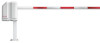
The Chamberlain Group, Inc. 845 Larch Avenue Elmhurst, Illinois 60126-1196 www.liftmaster.com MADCBB, MATDCBB, MASDCBB, & MASTDCBB HEAVY-DUTY DC BARRIER GATE OPERATOR OWNER'S MANUAL RREINCACELDUIIVDOEEDR MEGA ARM TOWER & MEGA SPRINT TOWER MEGA ARM & MEGA SPRINT IMPORTANT: Read and understand - LiftMaster MA | Owners Manual - Page 2
OPERATION AND MAINTENANCE Important Safety Instructions General Service Shear Pin Replacement Battery ADDITIONAL FEATURES Suggested Loop Sensor Locations Trap Instructions Sequence Access Management System (SAMS) with "Memory" Control Board Layout TROUBLESHOOTING Battery Checkout Gate Not Operating - LiftMaster MA | Owners Manual - Page 3
servicing the general public, in which unauthorized access is prevented via supervision by security personnel. SAFETY ACCESSORY SELECTION All UL325 compliant LiftMaster gate for a control requiring continuous pressure to operate the operator open and close. Type E: Built-in audio alarm. Examples - LiftMaster MA | Owners Manual - Page 4
Rollers • Photoelectric Sensors • Vertical Posts • Instructional and Precautionary Signage 4. Install the gate operator only when: a. The operator is appropriate for the construction and the usage class of the gate. b. All openings of a horizontal slide gate are guarded or screened from the - LiftMaster MA | Owners Manual - Page 5
• Full service controller with eight inputs and LED indicators for loops, card reader, radio, etc. • Reversible arm direction for right or left handed operation. • Instant Reverse Device (IRD) monitor senses obstructions during motion. • Fail safe (auto open on AC power failure). • Raise gate input - LiftMaster MA | Owners Manual - Page 6
installed to fit the 3-1/2" x 3-1/2" opening in the pedestal base plate or the 10-1/4" x 8-1/4" opening in the tower base plate. The operator 6" 3-1/2" 12" 9" 8" TOP VIEW OF TOWER FOOTPRINT 5-1/4" 7-1/8" (gate arm bracket) 7-1/8" (concrete pad) 3-1/2" 9-7/8" 13-1/2" 10-1/4" 8-1/4" 6" - LiftMaster MA | Owners Manual - Page 7
) 1/2" x 6" (base plate) 1/2" x 6" INSTALL THE BARRIER ARM 1 Line up the holes in the barrier arm with the slotted holes in gate arm bracket. 2 Insert the bolts through the barrier arm and gate arm bracket. 3 Secure with the flat washers and nylon nuts (It is recommended to use ONLY nylon nuts - LiftMaster MA | Owners Manual - Page 8
locking-out the power via the operator power switch. Upon completion of maintenance the area MUST be cleared and secured, at that time the operator may be returned to service insulated wire only. NOTE: Do not connect the batteries until instructed. 120 VAC 1 Ensure your main power is OFF before - LiftMaster MA | Owners Manual - Page 9
indicators to show input command activity. J5 Wiring Inputs on the control board C18 U18 C15 F MANUAL 1 2 3 4 5 6 7 8 9 1Ø 11 12 OPEN Q2 J5 S3 T2 T4 T6 T8 T1 T3 T5 T7 CLOSE OPEN 1 OPEN 2 OPEN 3 R21 AUX 4 SAFETY 5 CLOSE 6 BACK 7 SHADOW 8 C16 D15 D16 D17 D18 D19 D22 D23 D24 3 R24 - LiftMaster MA | Owners Manual - Page 10
relay when a tail-gate is detected by the close loop ANTI TAIL-GATE ALARM. Relay will pulse relay when arm reaches full open position. Relay will only without installing the batteries. Replace batteries in pairs using LiftMaster MBAT or 29-NP712 batteries. Failure to install batteries correctly - LiftMaster MA | Owners Manual - Page 11
second to inform the other that a closing obstruction has occurred and for it to reverse and open. SET switches on S2, 1-8 the same on both gates. FIGURE 1 Primary J5 1 2 3 4 5 6 7 8 9 10 11 12 Close Open Common 1 2 3 4 5 6 7 8 9 10 11 12 Second J5 FIGURE 2 RX GND TX 12 34 Primary J3 Second J3 - LiftMaster MA | Owners Manual - Page 12
R9 R8 R7 R6 R5 R4 R3 D9 R2 C18 U18 C15 DJ121Ø 1 AUX LIMITS M/S J3 R14 S3 MANUAL R18 Q2 OPEN 1 2 3 4 5 6 7 8 9 1Ø 11 12 J5 T2 T1 T4 T3 T6 T5 T8 Steps 2 and 3 for each remote control that will be used to operate the gate. TO ERASE ALL REMOTE CONTROL CODES 1 Press and hold the "learn" button - LiftMaster MA | Owners Manual - Page 13
FAST RUN TIMER (FULL SPEED RUN TIMER) DIP Switch S1-1 to S1-4 When the gate operator activates, it ramps up and slows down for a fixed amount of time, but , and using the Clutch Option; when the barrier arm is manually forced UP (OPEN), the barrier arm will automatically CLOSE. If the Close Loop - LiftMaster MA | Owners Manual - Page 14
Switch S2-1 to S2-5 The S2-1 to S2-5 DIP switches will set the period of time the gate remains opened after reaching the OPEN position. Each DIP switch represents the number of seconds the gate will remain OPEN before CLOSING. With the S2-3 DIP switch in the ON (factory default) position, there are - LiftMaster MA | Owners Manual - Page 15
gate operator properly can increase the risk of INJURY or DEATH. 7. The entrance is for vehicles ONLY. Pedestrians MUST use separate entrance. 8. Disconnect ALL power BEFORE performing ANY maintenance. 9. ALL maintenance MUST be performed by a LiftMaster professional. 10. SAVE THESE INSTRUCTIONS - LiftMaster MA | Owners Manual - Page 16
Battery, Standard"). BATTERY REPLACEMENT Service Kits are available for battery replacement. Please contact Technical Support (see back of this document for contact information). Replace the batteries with LiftMaster P/N MBAT batteries. Replace in pairs. BATTERY MAINTENANCE / TESTING The batteries - LiftMaster MA | Owners Manual - Page 17
closing timer is to be used, use ONLY on a dedicated free exit. • Close loop must be centered under gate arm. Back Away Loop (Free Exit) Mega Arm FREE EXIT ON VEHICLE APPROACH Gate will open when sensed by exit loop and then close once the close loop is cleared. If the vehicle pulls - LiftMaster MA | Owners Manual - Page 18
ADDITIONAL FEATURES » TRAP INSTRUCTIONS TRAP INSTRUCTIONS INSTALL THE K1 AUXILIARY RELAY Open the trap gate using the access device. • When the trap gate is open, activate the close loop on the trap operator. The trap gate will close and the second gate should open. • When the second gate is open - LiftMaster MA | Owners Manual - Page 19
, leave S1-6, S1-8 OFF (this will keep the K1 relay latched down until the arm reaches the down position. This will keep the other gate operator locked open or teeth locked down until the arm closes completely). • In this mode, if the arm senses an impact, the K1 relay will stay energized holding - LiftMaster MA | Owners Manual - Page 20
running properly. D12: Battery status. See diagnostic procedures. D14: AC power indicator. Shows that AC power is present. S3: Manual open. To allow gate to be opened or closed during service of operator. Keep in the "Close" position for normal operation. F3: 10 amp ATO type fuse for 24 Vac input - LiftMaster MA | Owners Manual - Page 21
TROUBLESHOOTING » BATTERY CHECKOUT + GATE NOT OPERATING WARNING - DISCONNECT BATTERIES AND AC POWER BEFORE SERVICING ANY MECHANICAL OR MOVING COMPONENTS. BATTERY CHECKOUT When the batteries become weak the gate Vdc. NOTE: If LED D12 does light, gate will open to conserve batteries in this test or in - LiftMaster MA | Owners Manual - Page 22
Belt 8 MA008 Reducer Pulley 9 MA009 Motor Pulley 10 MA010 Gate Arm Bracket 11 MA011 Magnet 12 MA012 Cam Arm 13 MA013 Shear Pin PARTS SHIPPED ITEM MEGA ARM Operator Controller Operator Cover Installation and Service Manual Arm Bolts with Washers Nylon Nuts 7AH Batteries ITEM PART - LiftMaster MA | Owners Manual - Page 23
CONTROLS Chamberlain offers a variety of LiftMaster Security✚® and Passport™ remote OPEN controls to satisfy your application needs. surge suppressor, wire jumper, duplex box covers and detailed instructions. SPRINT OPERATORS ONLY SPRINT GATE ARM 8' Padded Safety Arm, yellow. Model SP8 REPLACEMENT - LiftMaster MA | Owners Manual - Page 24
at any time on gate arms and chassis. SERVICE INFORMATION SIMPLY DIAL OUR TOLL FREE NUMBER: 1-800-528-2806 www.liftmaster.com WHEN ORDERING REPAIR PARTS, ALWAYS GIVE THE FOLLOWING INFORMATION: • PART NUMBER • PART NAME • MODEL NUMBER ADDRESS ORDERS TO: THE CHAMBERLAIN GROUP, INC. Technical Support
-
 1
1 -
 2
2 -
 3
3 -
 4
4 -
 5
5 -
 6
6 -
 7
7 -
8
-
9
-
10
-
11
-
12
-
13
-
14
-
15
-
16
-
17
-
18
-
19
-
20
-
21
-
22
-
23
-
24
 |
 |

MADCBB, MATDCBB,
MASDCBB, & MASTDCBB
HEAVY-DUTY DC BARRIER GATE OPERATOR
OWNER'S MANUAL
RADIO
RECEIVER
INCLUDED
IMPORTANT:
Read and understand Warranty Page first. Batteries (included) MUST be connected for proper
operation of operator. Use (2) LiftMaster 12 Vdc 7AH (Part # MBAT).
MEGA ARM &
MEGA SPRINT
MEGA ARM TOWER &
MEGA SPRINT TOWER
The Chamberlain Group, Inc.
845 Larch Avenue
Elmhurst, Illinois 60126-1196
www.liftmaster.com