LiftMaster EL2000SS EL2000SS Installation Manual - Page 2
Installation And Service Information Is As Near, As Your Telephone
 |
View all LiftMaster EL2000SS manuals
Add to My Manuals
Save this manual to your list of manuals |
Page 2 highlights
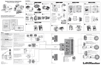
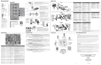
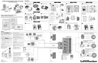
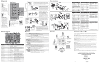
Wiring (continued) Input Board Exit Request Common Use 18-24 AWG CONNECTING A KEY SWITCH/PIR/REX Any auxiliary opening device such as a key switch or PIR (Passive Infrared Device), or an REX (Exit Request Button) that provides normally open contact closure can be hooked up to the Door Input terminals. Common Door Status Use 18-24 AWG CONNECTING A DOOR SENSING DEVICE The units can monitor the position of up to four doors/gates and may react to a change in their status with one of the relays (not set as a control relay). For example, if a door is forced open or is held open after its relay deactivates, the unit will record the breach in its transactions and can perform the following actions: • Energize a relay to activate an alarm device such as a siren, light or CCTV camera. • Main use is to terminate strike time early. NOTE: Door sensing device should provide contact closure when door is closed. Additional sensing devices can be connected to any of the 4 Door Stat inputs. 20-Pin to Control Board TERMINAL BLOCK CONNECTIONS 1 Door 1 - Exit Request and Door Status 2 Door 2 - Exit Request and Door Status 3 Door 3 - Exit Request and Door Status 4 Door 4 - Exit Request and Door Status 5 Postal Lock - Input 6 Auto Call - Input 7 Power - 12 Vac Input DO NOT overload the removable terminal block connectors. One wire per hole. Control Board TYPE 1 LED 2 Connector 3 Connector 4 Connector 5 Connector 6 Connector 7 Connector 8 LED 9 LED 10 LED 11 Connector 12 Connector 13 Connector 14 Connector 15 Connector 16 Connector 17 Switch 18 LED 19 LED 20 Connector 21 Connector 22 Switch BOARD LABEL D300 J405 J500 J406 J201 J403 J401 D2 D102 D153 J301 J404 J407 J400 J300 BT300 SW300 D513 D514 J402 J200 SW500 EL25 X X X X X X X X X X EL2000 X X X X X X X X X X X NAME PWR LED 20-Pin Connector to IO Input Board LCD PWR EL25 = LED BOTTOM KEYPAD EL2000 = LED keypad MIC 14-Pin Connector to Output Board KEYPAD Local Mode RES DAA OFF HOOK TELCO DAA OFF HOOK Direct Connect (Serial Port) X X LED Power Supply X X Module Device (3,4) X X Module Device (1,2) X LCD Data X X Battery X X OV/UV Reset X X Over-Voltage (OV) X X Under-Voltage (UV) X LED TOP KEYPAD X X Main Speaker X X Soft Reboot DESCRIPTION Indicates unit is receiving power. Connector to IO input board. The IO input board contains all REX inputs, Provides power to LCD display. For the EL25 provides power to bottom lighted LEDs for the main keypad. On the EL2000 this is the top lighted LEDs for main keypad. Microphone connector Connector to the output board. The output board contains the resident, Telco and dry contact relays. Connector for the main keypad. Unit supplying central office power to resident. Resident side of circuit is off hook. Telco side of circuit is off hook. Used for direct connect and hand-held programming and real time monitoring. Connect a module (Wiegand or RF) device here. The device address becomes 3 (RF or Wiegand-J1) or 4 (Wiegand-J2). Connect a module (Wiegand or RF) device here. The device address becomes 1 (RF or Wiegand-J1) or 2 (Wiegand-J2). Data wires for LCD display. Battery used to back-up the unit's real time clock. Switch to turn off OV/UV LEDs. This button will turn off the OV/UV LEDs momentarily. If a poor power condition still exists then the OV or UV LEDs may turn on again. Over-Voltage LED. Turns on when the unit detects an over voltage of 16.5 Vac or 22.3 Vdc at power block J1. Measure the voltage at power block J1 to confirm. Under-Voltage LED. Turns on when the unit detects an under voltage of 9.5 Vac or 10.2 Vdc at power block J1. Measure the voltage at power block J1 to confirm. For the EL25, provides power to the top lighted LEDs for main keypad. Main speaker Reboots firmware without removing power. N.C. Switch CONNECTING A POSTAL LOCK SWITCH (EL25 ONLY) The post office requires installation of a postal lock if postal carriers do not have access to a controlled area. Contact the local post office and arrange for them to install the postal lock while you are on site. The postal lock requires a switch to activate one of the four relays (Configurable with programming number 69, in the Keypad Programming manual). NOTE: In the EL2000 models, the postal lock switch is pre-wired. Loop Detector CONNECTING THE AUTOCALL FEATURE Using the AutoCall feature, the unit will automatically call the main residence phone when a driveway sensor is activated (any device that provides a contact closure). For example, when a visitor drives over a loop sensor that is connected to the AutoCall feature, the unit will call the main residence phone automatically so the visitor can speak to the resident without pressing the call button on the unit. AC Power 12 Vac or 16 Vdc 110 Vac Dedicated Outlet Dedicated 10 Amp Minimum Circuit CONNECTING POWER TO THE UNIT The 110 Vac outlet must be dedicated to the unit only to be sure the unit is properly grounded. This outlet should be wired back to its own 10 Amp minimum circuit breaker. This will prevent two problems: • Other equipment cannot introduce spikes, noise, surges or dips into the power circuit. • The system's operation will not be affected if any other equipment develops a short circuit across the power line. Connect the transformer into a 110 Vac outlet after all connections have been made. Any other type of outlet will cause damage to the system. CONNECTING AN INTERNAL CAMERA (CCTV) An optional CCTV (Close Circuit Television) camera can be installed inside the unit. Refer to instructions supplied with the camera kit for more information. Home Entertainment System OR RG-59u Coaxial Cable 1000 Feet Maximum (Monitor with a .25 volt p-p composite signal sensitivity) A Closed Circuit Monitor Card Reader is Wired to Device 1 CONNECTING A RADIO FREQUENCY MODULE An optional radio frequency module and a remote antenna can be installed if the residents will access a controlled area with a transmitter. Refer to instructions supplied with the optional RF Module for more information. NOTE: The remote can control 1-4 doors. Avoid any metallic surface around the antenna. RF Module(s) will fit in positions J400 (Device 1) and/or J407 (Device 3) Remote Antenna RG-6 Coaxial Cable 100 Feet Maximum Blue (Insulate this wire) Shield (Attach to the unit ground only) Wiegand Module Kit WIEGAND CARD READER/KEYPAD Wiegand card readers and keypads can be connected to either of 2 optional Wiegand modules that can be placed in the unit. Each Wiegand module supports two card readers/keypads. Some Wiegand card reader/keypads have a sixth blue wire. Do not connect this blue wire to the unit. Insulate this wire from the unit to prevent a short. For more information, refer to Wiegand device instructions. Wiegand Modules will fit in J400 as Device 1 (J1) and 2 (J2) and/or J407 as Device 3 (J1) and 4 (J2). Four mounting screws per board are required. Troubleshooting WIRING Check for correct length and AWG of wires. Check that wires are correctly inserted into the terminal blocks (not loose, no two sharing the same position). Check board markings for correct terminal block placements. Make sure high voltage and Telco wires do not share the same conduit. Use metal conduit. Do not use PVC. NO POWER TO UNIT Check power at source. Power must come from a dedicated 110 Vac outlet. The transformer's outlet should be wired to its own circuit breaker. Check SYS PWR LED indicators. If UV or OV are lit, press PWR MON RST button. If either of those two LEDs are still lit, check transformer and outlet. DOOR STRIKES/MAGLOCKS/GATE OPERATOR NOT WORKING Check power source. Strikes, Maglocks and Gate Operator must be powered independent from unit. Connect and test different Strike or Maglock. Make sure Strike or Maglock is not defective. Door Strike: Pin connections NO and COM at Relay terminal. Maglock: Pin connections NC and COM at Relay terminal. Gate Operator: Pin connections NO and COM at Relay terminal. POSTAL LOCK OR AUTOCALL Short IN and COM pin connections to verify functionality. If wiring is correct and device still does not work, DEVICE NOT WORKING contact technical support. CARD READER NOT COMMUNICATING WITH UNIT Make sure Wiegand is configured to a door (program step 60). Check Wiegand reader module connections. Connect and test a functioning reader. Make sure reader is not defective. Did you add the card(s) to the database while in programming mode? Check card format compatibility. The unit is only compatible with 26 and 30-Bit. Review the transactions using Versa XS, if applicable, and check whether card failed. PHONE NOT FUNCTIONING WITH THE UNIT Did you wire the bypass board correctly? See Connecting To The Telco Line. Is bypass board switch set to OPERATE? Using an alarm system? See Connecting To The Telco Line. Using an alarm system on multiple unit configuration? See Connecting To The Telco Line. AUX OPEN/EXIT REQUEST DEVICE Short to verify functionality. NOT WORKING Did you assign a relay to the REX? See the unit's programming manual. Check connections at Door # terminal(s). Wires to COM and EXT REQ # connection. TRANSMITTER NOT WORKING Did you use the correct coaxial cable? Is the remote antenna installed correctly? Is it outside of the unit's enclosure? Did you add the transmitter(s) to the database while in programming mode? Only Passport or Homelink transmitters can be used. Repair Parts 46 5 EL25 21 1 12 2 11 3 8 13 7 10 9 14 11 22 15 19 17 20 16 PART DESCRIPTION 1 Silver Cover Nickel Cover Mist Gray Cover 2 Camera Lens Black PART NO. 93D341 93D341-1 93D341-2 108B81 3 Camera Lens Clear 108B81-1 4 Call Button Activator, Silver 101A159 Call Button Activator, Nickel 101A159-1 Call Button Activator, Mist Gray 101A159-2 5 Call Button E-Ring 158A94 PART DESCRIPTION 9 Key 10 Speaker 11 LED Assembly 12 Microphone Assembly 13 Key Pad Gasket 14 Keypad PART NO. EL25KEY 2B639 2B721 2B692 84C87 180D236 PART DESCRIPTION 18 Silver Mounting Plate Nickel Mounting Plate Mist Gray Mounting Plate 19 20-Pin Cable 20 14-Pin Cable 21 Call Button Board 22 Direct Connect Cable PART NO. 2C607 2C607-1 2C607-2 2B705 2B704 2B731 2B747 6 Call Button Spring 177A166 15 Main Board 18 7 Gasket 84B81-1 16 Output Board 2B735 2B737 8 Lock 2B809 17 Input Board 2B736 EL2000 2 1 20 19 23 22 8 3 17 16 9 13 21 18 11 6 4 7 10 5 12 14 15 PART DESCRIPTION 1 Assembly Display and Display Board 2 Display Cables Kit 3 Output Board 4 Input Board 5 Main Board 6 20-Pin Cable 7 14-Pin Cable 8 Housing, Black Housing Assembly, Gray Housing Assembly, Nickel 9 Door Interconnect Cables Kit PART NO. 41B989 41B990 2B737 2B736 2B735 2B705 2B704 41B991 41B992 41B993 41B994 PART DESCRIPTION 10 Speaker 11 Call Button Board 12 Postal Lock Switch 13 Interconnect Board 14 Lock and Keys 15 Replacement Key 16 Keypad 17 Keypad Gasket 18 Microphone Assembly 19 Entry LED Board PART NO. 2B639 41B995 41B996 41B997 41B999 41B12 180D236 84C87 2B692 41B998 PART DESCRIPTION 20 Keypad Light Board 21 Camera Lens, Black Camera Lens, Clear 22 Gasket and Display Window (Clear) Gasket and Display Window (Black) 23 Faceplate Black, No Window Faceplate Gray, No Window Faceplate Nickel, No Window PART NO. 41B773-1 108B81 108B81-1 41B1000 41B1001 41B1002 41B1003 41B1004 EL2000SS PART DESCRIPTION PART NO. PART DESCRIPTION PART NO. 19 12 1 15 16 3 8 7 1 Assembly Display and Display Board 2 Output Board 3 Input Board 41B989 2B737 2B736 10 Postal Lock Switch 11 Interconnect Board 12 Lock and Keys 41B996 41B997 SNRLOCK 14 13 2 9 11 4 18 5 17 10 6 4 Main Board 5 20-Pin Cable 6 14-Pin Cable 7 Housing Assembly, Replacement 8 Electric Parts Kit* 9 Speaker 2B735 2B705 2B704 K75-37503 K75-37500 2B639 13 Keypad 14 Keypad Gasket 15 Microphone Assembly 16 Entry LED Board Kit 17 Keypad Light Board 18 Camera and Display Lens Kit 19 Faceplate Stainless Steel 180D236 84C87 2B692 41B998 41B773-1 K75-37505 K75-37369 * Electric Parts Kit includes: call button, display cables, interconnect, and extension cables (for keypad, light, and speakers) Accessories FCC & DOC Requirements Wiegand Module Kit WOMODKT EL25 Camera Kits EL25BWCAMKT (Black & White Camera) EL25DVRCAMKT (Low Lux DVR Color Camera) EL25CAMKT (Color Camera) EL2000SS EL2000 Camera Kits EL2000BWCAMKT (Black & White Camera) EL2000DVRCAMKT (Low Lux DVR Color Camera) EL2000CAMKT (Color Camera) RF Module Kit RFMODKT (390 MHz) RFMODKT3 (315 MHz) EL2000 Wiegand Remote Keypad ESSWOKSG EL25 Heater Kit ELHTRKT EL2000 ONLY Wiegand Remote Keypad/Prox Combo HIDWOKPRO FCC REQUIREMENTS The units comply with Part 68 of the FCC Rules. The label affixed to this equipment contains, among other information, the FCC Registration Number and Ringer Equivalence Number (REN) for this equipment. You must, upon request, provide this information to your telephone company. The REN is useful to determine the quantity of devices you may connect to your telephone line and still have all of those devices ring when your telephone number is called. In most, but not all areas, the sum of the RENs of all devices connected to one line should not exceed five (5.0). To be certain of the number of devices you may connect to your line, as determined by the REN, you should contact your local telephone company. They will tell you what the maximum REN is for your calling area. The following jacks must be ordered from the telephone company in order to interconnect this equipment with the public communication network: None. If your unit causes harm to the telephone network, the Telephone Company may discontinue your service temporarily. If possible, they will notify you in advance. If advance notice is not practical, you will be notified as soon as possible. You will be informed of your right to file a complaint with the FCC. Your Telephone Company may make changes in its facilities, equipment, operations or procedures that could affect the proper functioning of your equipment. If they do you will be notified, in advance, to give you an opportunity to maintain uninterrupted telephone service. Connections to party lines are subject to state tariffs. Contact your local telephone company if you plan to use this equipment on party lines. This equipment cannot be used on public coin service lines provided by the telephone company. DOC REQUIREMENTS NOTICE: The Canadian Department of Communications label identifies certified equipment. This certification means that the equipment meets certain telecommunications network protective, operational, and safety requirements. The Department does not guarantee the equipment will operate to the user's satisfaction. Before installing this equipment, users should ensure that it is permissible to be connected to the facilities of the local Telecommunications Company. The equipment must also be installed using an acceptable method of connection. In some cases, the company's inside wiring associated with single line individual service may be extended by means of a certified connector assemble (telephone extension cord). The customer should be aware that compliance with the above conditions may not prevent degradation of service in some situations. Repairs to certified equipment should be made by an authorized Canadian maintenance facility designated by the supplier. Any repairs or alterations made by the user to this equipment, or equipment malfunctions, may give the telecommunications company cause to request the user to disconnect the equipment. Users should ensure for their own protection that the electrical ground connections of the power utility, telephone lines, and internal metallic water pipe unit, if present, are connected together. This precaution may be particularly important in rural areas. CAUTION: Users should not attempt to make such connections themselves, but should contact the appropriate electric inspection authority, or electrician, as appropriate. The Load Number (LN) assigned to each terminal device denotes the percentage of the total load to be connected to a telephone loop, which is used by the device, to prevent overloading. The termination on a loop may consist of any combination of devices subject only to the requirement that the total of the Load Numbers of all the devices does not exceed 100. The Load Number for EL Series Units is 3. Versa XS Software VERSWR20 INSTALLATION AND SERVICE INFORMATION IS AS NEAR AS YOUR TELEPHONE WHEN ORDERING REPAIR PARTS, ALWAYS GIVE THE FOLLOWING INFORMATION: • PART NUMBER • PART NAME • MODEL NUMBER 1.800.528.2806 LiftMaster.com 114A4170E © 2014, LiftMaster All Rights Reserved
-
 1
1 -
 2
2 -
 3
3 -
 4
4
 |
 |
