LiftMaster EL2000SS EL2000SS Installation Manual
LiftMaster EL2000SS Manual
 |
View all LiftMaster EL2000SS manuals
Add to My Manuals
Save this manual to your list of manuals |
LiftMaster EL2000SS manual content summary:
- LiftMaster EL2000SS | EL2000SS Installation Manual - Page 1
2 Unplug the two main harnesses. (Optional) EL2000SS 1 The EL2000SS is for flush mounted applications. Turn key clockwise LiftMaster 845 Larch Avenue Elmhurst, IL 60126-1196 LiftMaster each unit wired in the series. See Keypad Programming manual. CONNECTING TO AN INTERNAL PHONE SYSTEM The units can - LiftMaster EL2000SS | EL2000SS Installation Manual - Page 2
manual problems: instructions instructions supports instructions. Wiegand Modules will fit in J400 as Device 1 (J1) and 2 (J2) and/or J407 as Device 3 (J1) and 4 (J2). Four mounting screws per board are required. Troubleshooting support manual EL2000SS EL2000SS service service service service service SERVICE - LiftMaster EL2000SS | EL2000SS Installation Manual - Page 3
. 3 Clavier 2 Support J406 AFFICHAGE ACL J201 antihoraire, en position verrouillée. EL2000 EL2000SS Câblage Déconnectez l'alimentation au niveau services publics, contactez les compagnies de AVERTISSEMENT localisation de services LiftMaster 845 Larch Avenue Elmhurst, IL 60126-1196 LiftMaster - LiftMaster EL2000SS | EL2000SS Installation Manual - Page 4
érieur de l'unité. Consultez les instructions fournies avec la caméra pour 41B1000 41B1001 41B1002 41B1003 41B1004 EL2000SS DESCRIPTION DE LA PIÈ de la compagnie avec service individuel de ligne unique peut LiftMaster.com 114A4170E © 2014, LiftMaster All Rights Reserved Tous Droits Réservés
-
 1
1 -
 2
2 -
 3
3 -
 4
4
 |
 |
Installation
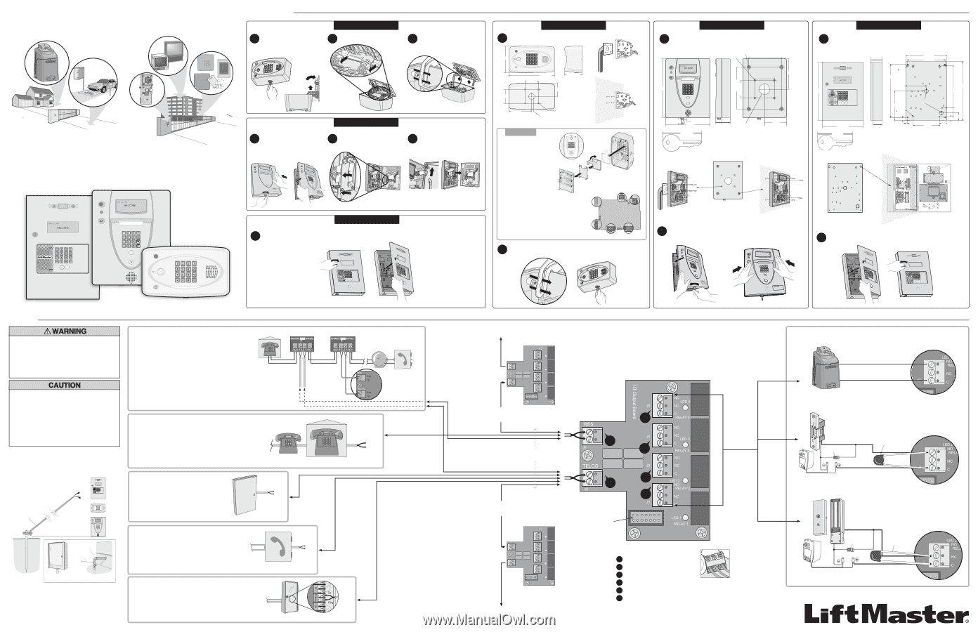
Telephone Entry/Access Control System
Models EL25, EL2000, and EL2000SS
EL25
EL2000
Optional modules let you expand the system to fit your specific needs. The Wiegand output module lets you add card readers and/or remote
keypads. Our RF module provides convenient access through gates or doors with Passport™ transmitters. Plus, the system is now designed to
automatically detect the addition and location of each new plug-in module, making installation and programming faster and easier than ever before.
RESIDENTIAL AND COMMERCIAL TELEPHONE ENTRY SYSTEMS
WITH EXPANDED CAPACITY AND ENHANCED VERSATILITY
3
4
5
6
2
1
Normally Open
Common
Use 18-24 AWG
Normally Open
Siemens S10K30 MOV
(Metal Oxide Varistor)
or equivalent.
Common
Use 18-22 AWG
1N4005 diode
or equivalent.
AC or DC Power for
Door Strike (Not Provided)
Normally Closed
Siemens S10K30 MOV
(Metal Oxide Varistor)
or equivalent.
Common
Use 18-22 AWG
1N4005 diode
or equivalent.
AC or DC Power for
Door Strike (Not Provided)
Home Phone
Bypass Board
for Unit 1
Ring
Ring
Ring
Tip
Tip
Tip
Bypass Board
for Unit 2
Home Phone
Unit ID 2
Output Board
Telco Entrance Box
Demarcation Point
Alarm SystemPosition
(Not Provided)
Sentex Ovation Unit
Telco Entrance Box
Demarcation Point
Ring
Tip
Ring
Tip
Internal Phone System
Analog Trunk
Green Ground Wire
Earth Ground Rod
12 ft Maximum
Ground Wire
Metallic Cold
Water Pipe
Electrical Panel
Alternative Grounding Solutions
OR
OR
Output Board
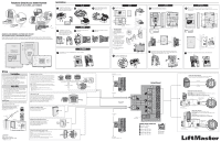
CONNECTING TO THE TELCO LINE
The bypass board allows the unit(s) to be disconnected without interrupting
normal telephone operation. If the unit(s) will be used in conjunction with an
alarm system, you must connect the telephone line to the alarm system first.
If the units are not connected in this order, they will not operate properly.
Up to 7 units can share the same phone line. You must program the unit id’s
for each unit wired in the series. See Keypad Programming manual.
The bypass board (located inside the property) allows access to the phone in
case the unit(s) fail.
NOTE:
Installation where fiber optic phone lines are present may require
additional modifications from your telephone provider. Contact your provider
for more information.
•
When a unit is
in use
, the bypass switch must be set to the
operate
position.
•
When a unit is
disconnected
, the bypass switch must be set to the
bypass
position.
14-Pin to
Control Board
Ring
Ring
Tip
Tip
•
To AVOID damaging gas, power or other underground utility
lines, contact underground utility locating companies BEFORE
digging more than 18 inches (46 cm) deep.
•
Contact the building inspector’s office in the municipality where
you plan to install the unit for correct grounding materials and
installation procedures.
•
Ensure that the system is grounded properly. The units contain
a number of static sensitive components that can be damaged
by static discharge.
•
DO NOT ground the units to a pedestal post (gooseneck) if one
is used.
GROUND THE UNIT
Install an earth ground rod no further than 12 feet from the unit and
use a minimum of 12 gauge wire in most cases. The type and length
of earth ground rods vary by region.
NOTE:
Keep ground wire as straight as possible.
ALTERNATIVE GROUNDING SOLUTIONS
The unit may be grounded to a metallic or an
existing electrical system within
12' of the unit.
CONNECTING TO A DEDICATED TELCO LINE
Installation where fiber optic phone lines are present may
require additional modifications from your telephone
provider. Contact your provider for more information.
Up to 7 units may be installed. You must program the
unit id’s for each
unit wired in the series.
See Keypad Programming manual.
To next unit
(Unit ID 5 then Unit ID 4 etc.)
Unit ID 2
CONNECTING TO AN INTERNAL PHONE SYSTEM
The units can be wired to any
analog trunk
in an internal home phone
system.
Installation where fiber optic phone lines are present may require
additional modifications from your telephone provider. Contact your
provider for more information.
Up to 7 units may be installed. You must program the unit id’s for each
unit wired in the series. See Keypad Programming manual.
CONNECTING TO AN NPBI SYSTEM
Up to 7 units may be installed. You must program
the unit id's for each
unit wired in the series.
See Keypad Programming manual.
Disconnect power at the fuse box BEFORE proceeding. The unit
MUST be properly grounded and connected in accordance with
national and local electrical codes.
NOTE:
The unit should be on a
separate fused line of adequate capacity.
• A static discharge can damage circuit boards
•
NEVER run telco wires and high voltage wires in the same
conduit. The high voltage may interfere with the telco wires,
possibly causing the system to malfunction.
Wiring
CONNECTING A GATE OPERATOR
Refer to the gate operator manual for proper relay strike time. Additional
opening or exit devices can be connected to any of the 4 relays.
CONNECTING A MAGLOCK
The maglock can be connected to any of the 4 relays.
FOR AC POWER:
Install a Siemens S10K30 MOV (Metal Oxide Varistor)
or equivalent
FOR DC POWER:
Install a 1N4005 diode or equivalent.
DO NOT USE THE UNIT’S POWER SUPPLY FOR THE MAGLOCK.
CONNECTING TO A DOOR STRIKE LOCK
The door strike can be connected to any of the 4 relays.
FOR AC POWER:
Install a Siemens S10K30 MOV (Metal Oxide Varistor) or equivalent.
FOR DC POWER:
Install a 1N4005 diode or equivalent.
DO NOT USE THE UNIT’S POWER SUPPLY FOR THE DOOR STRIKE.
STAND ALONE SYSTEM
The unit can be a stand alone system that allows communication between
the unit and a resident’s phone. Connect a twisted wire (18-24 AWG) from
the RES terminal block on the unit's output board, to the resident's phone.
Up to 7 units can share the same phone line. You must program the unit id’s
for each
unit wired in the series. See Keypad Programming manual.
Only disable the Telco mode of the unit farthest away from the house. See
“Disable Telco Mode” in the Keypad Programming manual.
NOTE:
Ringer Equivalence Number (REN) of “5” maximum.
To next unit
(Unit ID 3, then Unit ID 4, etc.)
TERMINAL BLOCK CONNECTIONS
Resident - Tip/Ring
Telco - Tip/Ring
Relay 4, NO, NC, COM
Relay 3, NO, NC, COM
Relay 2, NO, NC, COM
Relay 1, NO, NC, COM
DO NOT overload the
removable terminal
block connectors.
One wire per hole.
1
2
3
4
5
6
Unit ID 6
For additional
units
For additional
units
To TELCO
To RES
Use 18-24 AWG
2 twisted pair
LiftMaster
845 Larch Avenue
Elmhurst, IL 60126-1196
LiftMaster.com
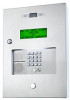
EL2000SS
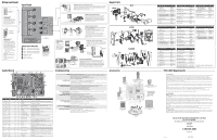
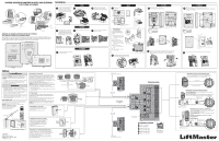
The EL25 is for surface mount
applications only. Unlock the unit and
open cover. Carefully lift mounting
plate up then slide out on hinges.
The EL2000 is for surface and
pedestal mount applications. Apply
pressure to the right-side of the unit.
While maintaining pressure, turn key
clockwise and open the cover.
Unplug the two main harnesses.
Line up notch with screw and push
hinge out. Remove the mounting
plate from the cover.
EL2000
EL25
Slide cover out of hinges to remove.
(Optional)
1
1
2
Unplug the two main harnesses.
(Optional)
2
3
3
The EL2000SS is for flush mounted applications. Turn key clockwise
and open the cover.
EL2000SS
1
VERTICAL MOUNTING
Rotate the keypad for vertical
mounting:
1
Disconnect all plugs from the
main circuit board. Remove
board (See control board
connections below).
2
Remove bracket (4 screws).
3
Rotate keypad 90° clockwise.
Bracket notch lines up with
ribbon cable on the keypad.
4
Reverse the sequence to
reassemble the unit.
5
Reconnect all plugs to the
control board.
Main Circuit
Board
Bracket
Keypad
1
2
3
6 in.
3-15/16 in.
3-1/16 in.
10-1/4 in.
3-1/16 in.
5-1/8 in.
Mounting Holes (4)
for 5/16 in.
1-1/16 in.
Conduit Hole
3 in.
J201 MIC
J402 LED
J402 SPKR
J402 LED
J406 LCD
J401 KEYPAD
PEDESTAL
WALL
Mount to a wall or pedestal.
EL2000
EL2000SS
EL25
OPTIONAL
5
4
1-5/8 in. Conduit Hole
Knockouts for 5/16 in.
Knockouts for 3/8 in.
15 in.
3-1/16 in.
9 in.
1-5/8 in.
1-15/16 in.
2 in.
12 in.
7 in.
9-1/2 in.
6 in.
3-1/16 in.
1-1/2 in.
1/2 in.
Mount to a wall or pedestal. Knock out
the desired mounting plugs using punch.
PEDESTAL
WALL
Knockouts
for 3/8 in.
Knockouts
for 5/16 in.
Turn the key counter-clockwise to the locked position. Close the cover.
Apply pressure to left-side until you hear a “click” sound. Apply pressure
to right-side of unit until you hear a “click” sound.
5
4
14.5 in.
14 in.
10.28 in.
7.25 in.
.75 in.
.485 in.
1 in.
2 in.
.188 in.
2 in.
1.5 in.
8 in.
5.625 in.
11.25 in.
16 in.
.5 in.
Conduit Holes
16 in.
1-15/16 in.
2.5 in.
11 1/4 in.
3.5 in.
Mount to a wall. Knock out the desired mounting plugs using punch.
Make sure the unit is properly sealed to prevent damage to the access control panel
from moisture.
WALL
Close the cover. Turn the key counter-clockwise to the locked position.
5
4
Lock the unit. Do not pinch wires
when closing and locking the unit.