LiftMaster CSW24UL Installation Manual
LiftMaster CSW24UL Manual
 |
View all LiftMaster CSW24UL manuals
Add to My Manuals
Save this manual to your list of manuals |
LiftMaster CSW24UL manual content summary:
- LiftMaster CSW24UL | Installation Manual - Page 1
COMMERCIAL DC VEHICULAR SWING GATE OPERATOR INSTALLATION MANUAL Model CSW24UL LiftMaster 300 Windsor Drive Oak Brook, IL 60523 • THIS PRODUCT IS TO BE INSTALLED AND SERVICED BY A TRAINED GATE SYSTEMS TECHNICIAN ONLY. • This model is for use on vehicular passage gates ONLY and not intended for use - LiftMaster CSW24UL | Installation Manual - Page 2
LEDs 41 Troubleshooting Chart 42 APPENDIX 45 Step 8 Solar Panel(s 45 SAMS Wiring with Relays Not Energized 49 Dual Gate Settings 49 Limit Setup with a Remote Control 50 WIRING DIAGRAM 51 REPAIR PARTS 52 ACCESSORIES 53 WARRANTY 55 SAFETY Safety Symbol and Signal Word Review When - LiftMaster CSW24UL | Installation Manual - Page 3
. Failure to adjust and retest the gate operator properly can increase the risk of INJURY or DEATH. l Use the emergency release ONLY when the gate is not moving. l KEEP GATES PROPERLY MAINTAINED. Read the owner's manual. Have a qualified service person make repairs to gate hardware. l The entrance - LiftMaster CSW24UL | Installation Manual - Page 4
The gate must be properly installed and work freely in both directions prior to the installation of the gate operator. 8. Permanently mounted access controls intended for users to activate, must be located at least 6 feet (1.8 m) away from any moving part of b. A hard wired contact sensor shall be - LiftMaster CSW24UL | Installation Manual - Page 5
grade and for barbed wire shall not be the manually 3.1.1.2 Except for the zone specified in Section 3.1.1.1, the distance operated gate is retrofitted with a powered gate operator. between a fixed object such as a wall, pillar or column, and a swing 1.6 A gate latch shall not be installed - LiftMaster CSW24UL | Installation Manual - Page 6
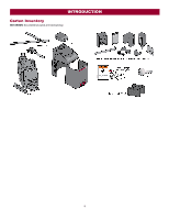
INTRODUCTION Carton Inventory NOT SHOWN: Documentation packet and hardware bag 6 - LiftMaster CSW24UL | Installation Manual - Page 7
3PHCONV is installed in the field, operator is rated 208/240/480/575 VAC, 4.8/4.2/2.1/1.7 A, 60 Hz, 1 PH System Operating Voltage 24 Vdc Transformer Run / Battery Backup Accessory Power 24 Vdc, 500mA max. for ON + SW (switched) Solar Power Max 24 Vdc at - LiftMaster CSW24UL | Installation Manual - Page 8
. Conduit must be UL approved for low and high voltage. Consider the operator placement BEFORE installing the pad or post. Safety Entrapment protection devices are required to protect against Gate MUST NOT hit or drag across ground Gate MUST swing freely and be supported entirely by its hinges. 8 - LiftMaster CSW24UL | Installation Manual - Page 9
an example of a standard installation. Compact Installation The illustration is an example of a compact installation. If the operator arm will hit an obstruction when the gate is in the open position, refer to LiftMaster.com for compact installation instructions. Entrapment protection devices must - LiftMaster CSW24UL | Installation Manual - Page 10
cm) deep. Step 1 Determine Location for Concrete Pad and Operator DO NOT run the operator until instructed. The illustration below shows the recommended dimensions for a standard installation. If these dimensions are not applicable for your installation refer to the chart on the following page for - LiftMaster CSW24UL | Installation Manual - Page 11
INSTALLATION Chart Installation Refer to the illustration to determine the measurements and location of the concrete pad. Dimension (A) thru (E) are from the center of one pivot point to - LiftMaster CSW24UL | Installation Manual - Page 12
Attachment CHECK the national and local building codes before installation. NOTE: When lifting the operator use the handle to avoid damaging the operator 1. Install the electrical conduit. 2. Pour a concrete pad (reinforced concrete is recommended). The concrete pad should be 6 inches (15.2 cm - LiftMaster CSW24UL | Installation Manual - Page 13
INSTALLATION Step 3 Position the Gate Bracket NOTE: It may be necessary to attach horizontal reinforcement to the gate before attaching the gate bracket. 1. Position the operator arm onto the output shaft so that the pin slides into the slot. 2. Measure 46" (116.8 cm) along the gate length from the - LiftMaster CSW24UL | Installation Manual - Page 14
INSTALLATION Step 5 Secure the Operator Arm Once the operator arm measurements are verified: 1. Weld the gate NOTE: Completely weld around the outer tubing and bracket. 5. Adjust the nuts on the operator arm so the operator arm fits snug on the output shaft yet still allows enough room to swivel (the - LiftMaster CSW24UL | Installation Manual - Page 15
LiftMaster operators to meet UL325 requirements, see Accessories. l Test ALL entrapment protection devices after completing installation of the operator. For testing instructions, refer to the manual , berms or other immovable objects). Illustrations provided by DASMA Gate Systems Safety Guide 15 - LiftMaster CSW24UL | Installation Manual - Page 16
INSTALLATION Wire Entrapment Protection Devices There are three options for wiring the entrapment protection devices depending on the specific device and how the device will function. Refer to the specific entrapment protection device manual for more information. These entrapment protection device - LiftMaster CSW24UL | Installation Manual - Page 17
NOT install ANY wiring or attempt to run the operator without or solar and battery) and locking-out the power via the operator power consulting the wiring diagram. switch. Upon completion of maintenance the area MUST be cleared and secured, at that time the unit may be returned to service. l ALL - LiftMaster CSW24UL | Installation Manual - Page 18
INSTALLATION All control wiring used to connect external devices to Class 2 circuits of the operator must be (QPTZ) Power-Limited Circuit Cables, Type CL2, CL2P, CL2R, or CL2X or other cable with equivalent or better electrical, mechanical, and flammability ratings. - LiftMaster CSW24UL | Installation Manual - Page 19
INSTALLATION AC power switch The AC Power switch on the operator will turn the incoming 120/240 Vac power ON or OFF. The operator's AC the other battery. 4. Connect the red wire from the J15 plug to the positive (+) terminal of the battery. 5. Connect the black wire from the J15 plug to the negative - LiftMaster CSW24UL | Installation Manual - Page 20
backup or solar installation. The 33AH application requires the Solar Harness Kit wire from the Solar Harness Kit to the black wire from the J15 plug as shown. Connect the other end of the black (-) wire to the negative (-) terminal on the battery as shown. 5. Turn ON AC power to the operator - LiftMaster CSW24UL | Installation Manual - Page 21
INSTALLATION Step 10 Dual gate setup There are two options for dual gate communication: wired or wireless. Follow the directions according to your application. Do not use wired and wireless communication simultaneously. Wired dual gate applications will have a longer battery standby time than - LiftMaster CSW24UL | Installation Manual - Page 22
INSTALLATION Wired setup Before digging, contact local underground utility locating companies. Use PVC conduit to prevent damage to cables. 1. Disconnect ALL power to the operator and unplug the J15 plug from the control board. 2. Trench across driveway to bury the shielded twisted pair cable. 3. - LiftMaster CSW24UL | Installation Manual - Page 23
11 Install the cover Before installing the cover, follow the instructions in the Adjustment section to adjust the limits and force. The operator cover cover and access door can be locked with the key. 1. Remove the operator arm from the output shaft by releasing the handle. 2. Align the tabs - LiftMaster CSW24UL | Installation Manual - Page 24
limits have been set and the required entrapment protection devices are installed. Initial Limits and Force Adjustment For dual gate applications the limits will have to be set for each operator. The gate MUST be attached to the operator before setting the limits and force. 1. Press and release the - LiftMaster CSW24UL | Installation Manual - Page 25
3. Perform the "Obstruction Test" after every limit and force setting adjustment (see below). Adjust the Limits After both limits are set and the operator is ready to run, one limit can be adjusted independently from the other by following steps 1-3 of the Initial Limit and Force Adjustment section - LiftMaster CSW24UL | Installation Manual - Page 26
Part 15 of the FCC rules and Industry Canada's license-exempt RSSs. Operation authority to operate the equipment. This device must be installed to installation. This equipment generates, uses and can radiate radio frequency energy and, if not installed and used in accordance with the instructions - LiftMaster CSW24UL | Installation Manual - Page 27
be programmed to ONE gate operator (see the KPW5/KPW250 manual for complete programming instructions). The Constant Pressure Override present. External entrapment protection devices include LiftMaster monitored photoelectric sensors and LiftMaster monitored wired and wireless edge sensors. Be sure - LiftMaster CSW24UL | Installation Manual - Page 28
on batteries). Cycle Quantity Feedback Use during servicing only to determine operator cycles. Use during servicing only to determine operator cycles. Use during servicing only to determine operator cycles. Use during servicing only to determine operator cycles. Fire Dept Open Input Typically - LiftMaster CSW24UL | Installation Manual - Page 29
See Status LED Chart in the Troubleshooting section. 11 DIAGNOSTICS Display: The diagnostics display will show the operator type, firmware version, and codes. The operator type will display as "SG" followed by a "24" which indicates the operator type as CSW24UL. The firmware version will show after - LiftMaster CSW24UL | Installation Manual - Page 30
operator arm to allow the gate to be opened and closed manually. On a dual gate application the handle must be released on both operators. sound (up to 5 minutes) and the operator will need to be reset. A. The operator arm or gate is incorrectly installed. B. The gate does not meet specifications. - LiftMaster CSW24UL | Installation Manual - Page 31
devices to Class 2 circuits of the operator must be (QPTZ) Power-Limited Circuit Cables, Type CL2, CL2P, CL2R, or CL2X or other cable with equivalent or better electrical, mechanical, and flammability ratings. External control devices Access control device wiring EXIT (2 Terminals) This input is - LiftMaster CSW24UL | Installation Manual - Page 32
(N.C.) output for maglocks. Relay activates prior to motor activation and during motor run. Relay is off when motor is off. Miscellaneous wiring Three button control station (4 Terminals) l OPEN and COM: Opens a closed gate. Hard open (maintained switch overrides external safeties and resets alarm - LiftMaster CSW24UL | Installation Manual - Page 33
AC/DC power to the main control board for 15 BATT: With loss of AC power, gate will remain in present position and seconds. operator is powered from batteries. 3. Connect power. The 1, 2, and 3 LEDs will flash in sequence until 3. EXIT FAIL switch: the main control board firmware revision is - LiftMaster CSW24UL | Installation Manual - Page 34
AC power or solar power is if gate is manually tampered with by actual cycles that the gate operator has run (in thousands), 000 and 9,999,000 cycles. After servicing, set Aux Relay switches back to wiring example RED/GREEN LIGHT FUNCTIONALITY Red light wired to AUX RELAY 1. Green light wired - LiftMaster CSW24UL | Installation Manual - Page 35
under the gate. l Holds open gate at open limit l Disregarded during gate motion l Pauses Timer-to-Close at Open Limit 9 Interrupt Loop Input (2 terminals) Loop wire connection for plug-in loop detector when loop is along the side of the gate. l Holds open gate at open limit l Stops and reverses - LiftMaster CSW24UL | Installation Manual - Page 36
MAINTAINED. Read the owner's manual. national and local electrical codes. NOTE: The operator should be on Have a qualified service person make repairs to gate hardware. a separate fused line of adequate capacity. l ALL maintenance MUST be performed by a LiftMaster professional. l NEVER let - LiftMaster CSW24UL | Installation Manual - Page 37
should be replaced every 3 years. Use only LiftMaster part 29-NP712 for replacement batteries. The batteries contain lead and need to be disposed of properly. The operator comes with two 7AH batteries. Two 33AH batteries (A12330SGLPK), Solar Harness Kit (K94-37236) with additional battery tray - LiftMaster CSW24UL | Installation Manual - Page 38
TROUBLESHOOTING To protect against fire and electrocution: l DISCONNECT power (AC or solar and battery) BEFORE installing or servicing operator. For continued protection against fire: l Replace ONLY with fuse of same type and rating. Diagnostic Codes NOTE: When cycling or disconnecting power (ac/ - LiftMaster CSW24UL | Installation Manual - Page 39
feature and then re-learn the second operator. Review monitored entrapment protection device connections. This swing gate operator will operate only after installation of a minimum of one external safety device in either the open or close direction. Check wired input on main control board; check for - LiftMaster CSW24UL | Installation Manual - Page 40
TROUBLESHOOTING Code 69 70 71 operators, either wired bus or radio. Ensure operator is powered. May have to erase the wireless communication and reprogram the two operators. Check the connections between the main board and the expansion board. Non-monitored contact closure devices are not supported - LiftMaster CSW24UL | Installation Manual - Page 41
TROUBLESHOOTING Control Board LEDs INPUT OFF POWER ON STATUS LEDS OFF state AC charger or Solar power available BATT OFF closing BATT LOW ACC PWR OVLD MEDIUM BLINK (1 Operator is in E1 (single blink per second) entrapment) FASTEST BLINK (8 The operator is in E2 (double blinks per second) - LiftMaster CSW24UL | Installation Manual - Page 42
of operator. Check operator's antenna and antenna wire. Check other wireless controls or devices. a. Check all Open and Close inputs for an active input b. Check all vehicle detector inputs for an active detector c. Battery voltage must be 23.0 Vdc or higher. Charge batteries by AC or solar power - LiftMaster CSW24UL | Installation Manual - Page 43
wired incorrectly SOLUTIONS a. Check all vehicle detector inputs for an active detector b. Check if AC power is available. If no AC power, then running on batteries and battery voltage must be 23.0 Vdc or higher. Charge batteries by AC or solar power or replace batteries. a. Review the operator. a. - LiftMaster CSW24UL | Installation Manual - Page 44
b. AUX Relay wiring incorrect c. Defective Expansion board Solar operator not getting enough cycles per day. Solar operator, insufficient standby time lock's NC and COM wires does not activate Solenoid, then replace Solenoid lock or Solenoid wiring (refer to Wiring Diagrams). a. Learn the limits - LiftMaster CSW24UL | Installation Manual - Page 45
batteries in the given zones as shown on the map below. Local geography and weather conditions may require additional solar panels. Solar powered gate operator installations are not supported in northern climates due to cold weather and a reduced number of hours of sunlight during the winter months - LiftMaster CSW24UL | Installation Manual - Page 46
APPENDIX Solar usage guide Typical System Standby Battery Current Consumption (mA) System voltage Main board with no radios programmed One or more LiftMaster® remote controls programmed MyQ® device or wireless dual gate programmed Expansion board Per loop detector LOOPDETLM (up to 3 loop detectors - LiftMaster CSW24UL | Installation Manual - Page 47
475 (144.8 m) 315 (96 m) Chart assumes: copper wire, 65°C, 5% drop, 30V nominal Installation Solar panel(s) MUST be installed facing south. Use a compass to determine direction. Below are general instructions for installing the solar panel(s). Your installation may vary slightly depending on the - LiftMaster CSW24UL | Installation Manual - Page 48
Wire the Batteries Solar panel applications require the Solar Harness Kit model K94-37236, see Accessories. APPENDIX Wire the solar panels Proceed to the Dual Gate section (if applicable) or proceed to the Adjustment section. 48 - LiftMaster CSW24UL | Installation Manual - Page 49
last and close first) Tandem Mode: OFF Synchronized Close: ON Bi-Part Delay: OFF (will open first and close last) Tandem Mode: OFF Synchronized Close: ON Expansion board FEATURE PRIMARY OPERATOR SECONDARY OPERATOR LiftMaster Internet Gateway Garage and Gate Monitor QUICK CLOSE Switch ON OFF - LiftMaster CSW24UL | Installation Manual - Page 50
gate open and close. This automatically sets the force. When limits are set properly the operator will automatically exit limit setting mode. Refer to the Adjustment section and follow the instructions for Fine Tune the Force and Obstruction Test . Perform the "Obstruction Test" after every limit - LiftMaster CSW24UL | Installation Manual - Page 51
WIRING DIAGRAM To protect against fire and electrocution: l DISCONNECT power (AC or solar and battery) BEFORE installing or servicing operator. For continued protection against fire: l Replace ONLY with fuse of same type and rating. 51 - LiftMaster CSW24UL | Installation Manual - Page 52
REPAIR PARTS NOT SHOWN K94-36540 Wiring Harness with product ID assembly K94-37205 Battery Harness (for 7AH batteries) K80-36544 Vent Plug (for top gear box) K80-36545 Vent Plug (for bottom gear box) K74-30762 Two 7AH batteries K94-37236 Solar Harness Kit K94-34778 Wire harness between main control - LiftMaster CSW24UL | Installation Manual - Page 53
needs. Single-button to 4-button, visor or key chain. The following remote controls are compatible with operators manufactured by LiftMaster after 1993. Contact your authorized LiftMaster dealer for additional details and options. 3-button remote control The 3-button remote control can be programmed - LiftMaster CSW24UL | Installation Manual - Page 54
For post-mounting models CSL24UL, CSW24UL CSW200UL and SL3000UL commercial gate operators. Posts not included. Model MPEL Remote antenna extension kit The remote antenna extension kit allows the antenna to be remotely installed. Model 86LM LiftMaster® internet gateway Internet enabled accessory - LiftMaster CSW24UL | Installation Manual - Page 55
[and that the CSW24UL is free from defect in materials and/or workmanship for a period of 7 year residential / 5 year commercial from the date of purchase]. The proper operation of this product is dependent on your compliance with the instructions regarding installation, operation, maintenance and - LiftMaster CSW24UL | Installation Manual - Page 56
300 Windsor Drive Oak Brook, IL 60523 LiftMaster.com © 2018, The Chamberlain Group, Inc. - All Rights Reserved 01-39380B
-
 1
1 -
 2
2 -
 3
3 -
 4
4 -
 5
5 -
 6
6 -
 7
7 -
8
-
9
-
10
-
11
-
12
-
13
-
14
-
15
-
16
-
17
-
18
-
19
-
20
-
21
-
22
-
23
-
24
-
25
-
26
-
27
-
28
-
29
-
30
-
31
-
32
-
33
-
34
-
35
-
36
-
37
-
38
-
39
-
40
-
41
-
42
-
43
-
44
-
45
-
46
-
47
-
48
-
49
-
50
-
51
-
52
-
53
-
54
-
55
-
56
 |
 |
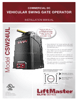
COMMERCIAL DC
VEHICULAR SWING GATE OPERATOR
INSTALLATION MANUAL
LiftMaster
300 Windsor Drive
Oak Brook, IL 60523
•
THIS PRODUCT IS TO BE INSTALLED AND
SERVICED BY A TRAINED GATE SYSTEMS
TECHNICIAN ONLY.
•
This model is for use on vehicular passage
gates ONLY and not intended for use on
pedestrian passage gates.
•
This model is intended for use in Class I, II,
III and IV vehicular swing gate applications.
•
Visit LiftMaster.com to locate a professional
installing dealer in your area.
•
This gate operator is compatible with MyQ
®
and Security+ 2.0
®
accessories.
Access installation and technical support
guides or register this product
Send it in
by texting the
photo to 71403.
Take a photo
of the camera
icon including the points (
).
1.
2.
Acce
guid
CSW24ULTECH
Model
CSW24UL