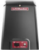
LiftMaster CSL24ULWK Installation Manual - English French Spanish - Page 7
CÓdigos De DiagnÓstico Del Lmwekitu - csl24ul
 |
View all LiftMaster CSL24ULWK manuals
Add to My Manuals
Save this manual to your list of manuals |
Page 7 highlights
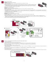
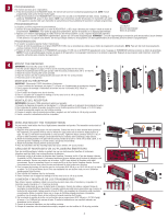
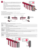
STEPS FOR TROUBLESHOOTING THE LMWEKITU Compatible Operators • CSW24U • CSL24U • LA500U • LA400U • LA412U • SL3000U • CSL24UL • • CSW200U • SL585U • LA500UL • • RSW12U • SL595U • LA400UL • • RSL12U • CSW24UL • LA412UL • CSW200UL RSW12UL RSL12UL SL3000UL • SL585UL • SL595UL LMWEKITU DIAGNOSTIC CODES 841 Non-monitored device detected on the wireless safety system 68 Wireless Edge triggered 69 Wireless Edge loss of monitoring Ensure that the installed edge is a Liftmaster product. Perform step 5. Normal response when an edge makes contact with an object. If it is constant, perform step 5. Check the testing steps below, paying attention to intermittent wire connections. Check the advanced diagnostic codes2 for further diagnostic information. 1 Available in firmware 4.2 or higher. 2 Available in firmware versions 3.5 and higher. ÉTAPES DE DÉPANNAGE DU LMWEKITU Actionneurs compatibles • CSW24U • LA412U • SL3000U • CSL24UL • CSL24U • CSW200U • SL585U • LA500UL • LA500U • RSW12U • SL595U • LA400UL • LA400U • RSL12U • CSW24UL • LA412UL • CSW200UL • RSW12UL • RSL12UL • SL3000UL • SL585UL • SL595UL CODES DE DIAGNOSTIC DU LMWEKITU 841 Dispositif non surveillé détecté sur le système S'assurer que la bordure de détection installée est un produit LiftMaster. Effectuer l'étape 5. de sécurité sans fil 68 Bordure sans fil déclenchée Réponse normale quand la bordure entre en contact avec un objet. Si le déclenchement est constant, effectuer l'étape 5. 69 Perte de surveillance de la bordure sans fil Vérifier les étapes de mises à l'essai ci-dessous en portant attention aux connexions de fil intermittentes. Vérifier les codes de diagnostic avancé2 pour plus d'information à ce sujet. 1 Offert dans le micrologiciel de version 4.2 ou plus. 2 Offert dans les versions logicielles 3.5 et plus.. PASOS PARA RESOLVER PROBLEMAS DEL LMWEKITU Operadores compatibles • CSW24U • CSL24U • LA500U • LA400U • LA412U • CSW200U • RSW12U • RSL12U • SL3000U • SL585U • SL595U • CSW24UL • CSL24UL • LA500UL • LA400UL • LA412UL • CSW200UL • RSW12UL • RSL12UL • SL3000UL • SL585UL • SL595UL CÓDIGOS DE DIAGNÓSTICO DEL LMWEKITU 841 Se detectó un dispositivo no monitoreado en el sistema de seguridad inalámbrico 68 Borde inalámbrico activado 69 Pérdida de monitoreo del borde inalámbrico Asegúrese de que el borde instalado sea un producto LiftMaster. Realice el Paso 5. Respuesta normal cuando un borde hace contacto con un objeto. Si es constante, realice el paso 5. Verifique los siguientes pasos de prueba, prestando atención a las conexiones de cables intermitentes. Para obtener más información de diagnóstico, consulte los códigos de diagnóstico avanzados2. 1 Disponible en la versión de firmware 4.2 o superiores. 2 Disponible en las versiones de firmware 3.5 y superiores. DETAILED STEP BY STEP TESTING THE LMWEKITU 1. Bypass the I2C Interface board and/or the expansion board. This provides a good means for troubleshooting by the process of elimination. a. Make sure that the receiver is plugged into the main board. i. If the receiver is plugged into the I2C interface board or into a two position plug on the expansion board, remove the harness between the main board and the I2C interface board (or expansion board). ii. Move the receiver harness from the other I2C interface board jack and plug it into the main board jack freed up by step i. 2. Activate the edge(s). a. On the edge's transmitter, the red LED should flash when the edge is pressed, and then again when it is released. i. If the LED in the transmitter doesn't flash: 1. Check the batteries. 2. Perform the steps outlined in Step 5. Control Board Carte logique Tarjeta de control b. On the receiver, the red LED should flash when the edge is pressed, and then it will flash about five seconds after the edge is released. i. If the LEDs in the receiver doesn't flash: 1. Perform the steps outlined in Step 6. 2. Perform the steps outlined in Step 7. 3. Perform the steps outlined in Step 8. c. On the logic board, either the close edge or the open edge (depending upon the switch setting of the transmitter). will flash when the edge is squeezed, until about 5 seconds after the edge is released. d. Repeat the tests for all edges. 3. Replace the I2C Interface board (if applicable). a. Plug the receiver into the I2C interface board. i. Move the receiver plug from the main board back to the free jack on the I2C interface board. ii. Remove all accessories including LOOPDETLM detectors from the expansion board. iii. Check to see that the power LED is flashing once a second. If it is not flashing: 1. Check the harness for correct insertion into the I2C interface board. 2. Ensure that the I2C interface board is properly installed onto the expansion board pin for pin. I2C Interface Board Carte d'interface I2C Tablero de interfaz I2C 6-32 x 1" (for metal) 6-32 x 1 po (pour le métal) 6-32 x 1 pulg. (para metal) OR OU O 3. Check to verify that the LED flashes without the I2C expansion board installed iv. Perform Step 2. If it doesn't work consider replacing 1. Expansion board 2. Expansion board harness v. Replace the loop detectors (LOOPDETLM) one at a time, performing Step 2 after each If needed Au besoin Si fuera necesario 6-19 x 1" (for plastic) 6-19 x 1 po (pour le plastique) 6-19 x 1 pulg. (para plástico) detector. If it stops working, exchange or replace the detector vi. Add one accessory at a time, performing step 2) after each accessory. If it stops working, exchange or replace the accessory. b. I2C Interface board is not used on those operators that don't have an expansion board installed. To Main Control Board À la carte mère Al tablero de control principal Expansion Board Carte d'extension Tablero de expansión c. Some expansion boards have an integrated second I2C connector. There is no need to install the I2C Interface boards on these operators. 7
-
 1
1 -
 2
2 -
 3
3 -
 4
4 -
 5
5 -
 6
6 -
 7
7 -
 8
8 -
 9
9 -
 10
10 -
 11
11 -
 12
12 -
13
-
14
-
15
-
16
-
17
-
18
-
19
-
20
 |
 |
