LiftMaster CSL24ULWK Installation Manual - English French Spanish
LiftMaster CSL24ULWK Manual
 |
View all LiftMaster CSL24ULWK manuals
Add to My Manuals
Save this manual to your list of manuals |
LiftMaster CSL24ULWK manual content summary:
- LiftMaster CSL24ULWK | Installation Manual - English French Spanish - Page 1
MONITORED WIRELESS EDGE KIT TROUSSE DE BORDURE SURVEILLÉE SANS FIL JUEGO DE BORDE INALÁMBRICO MONITOREADO Models/Modèles/Modelos LMWEKITU LMWETXU - LiftMaster CSL24ULWK | Installation Manual - English French Spanish - Page 2
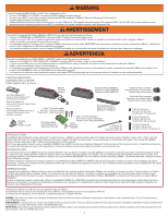
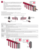
install with a clear line of sight between transmitter and receiver, objects in the path may reduce range). You can program up to 4 transmitters to the receiver. The kit works with LiftMaster monitored resistive edge sensors ONLY. Contact closure edge sensors are NOT supported in manual are - LiftMaster CSL24ULWK | Installation Manual - English French Spanish - Page 3
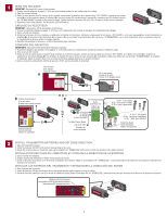
de la bordure. INSTALAR LAS BATERÍAS DEL TRANSMISOR Y ESTABLECER LA DIRECCIÓN DEL BORDE 1. Abra la carcasa del transmisor. 2. Instale las baterías. NO deje que la parte inferior del compartimento quede colgando junto a los cables. 3. Decida la dirección (apertura o cierre) en la que se instalará el - LiftMaster CSL24ULWK | Installation Manual - English French Spanish - Page 4
on to indicate programming mode. NOTE: To exit programming mode, press the raccordement de deux bordures de détection. 2. Fixer le support de montage à la barrière avec les vis fournies (3,28 pi) au-dessus du sol. Pour une installation sur une surface ronde, se servir d'attaches autobloquantes ( - LiftMaster CSL24ULWK | Installation Manual - English French Spanish - Page 5
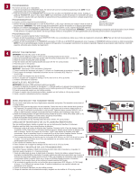
LED does not flash, check the transmitter and edge sensor for proper installation and wiring. Check that the edge direction is set correctly, see close (fail-secure) based on the operator setting (see the gate operator manual for more information). ÉTAT DE CHARGE DES PILES Une fois que la bordure - LiftMaster CSL24ULWK | Installation Manual - English French Spanish - Page 6
the transmitter and edge sensor for proper installation and wiring. • Check that the edge direction is set correctly, see page 3. The diagnostic display on the operator control board will display a code to indicate a problem. See the gate operator manual for instructions to display the codes. 46 - LiftMaster CSL24ULWK | Installation Manual - English French Spanish - Page 7
STEPS FOR TROUBLESHOOTING THE LMWEKITU Compatible Operators • CSW24U • CSL24U • LA500U • LA400U • LA412U • SL3000U • CSL24UL • • CSW200U • triggered 69 Wireless Edge loss of monitoring Ensure that the installed edge is a Liftmaster product. Perform step 5. Normal response when an edge makes - LiftMaster CSL24ULWK | Installation Manual - English French Spanish - Page 8
ée. c. Certaines cartes d'extension ont un deuxième connecteur I2C intégré. Nul besoin d'installer les cartes d'interface I2C sur ces actionneurs. 4. Remettre l'actionneur en service et surveiller son rendement. a. Surveiller le rendement à la longue. Consulter les entrées liées à la bordure - LiftMaster CSL24ULWK | Installation Manual - English French Spanish - Page 9
the other side of the edge are installed correctly and that their leads are not corroded. Replace the parts on the edge when complete. b. on the RECEIVER board. The red LED will come on to indicate programming mode. NOTE: To exit programming mode, press the learn button again. 9. How to test the - LiftMaster CSL24ULWK | Installation Manual - English French Spanish - Page 10
cables no estén corroídos. Reemplace las partes en el borde una vez que termine. b. manuales de apertura derecho y de apertura izquierdo a la misma vez. ii. Presione y suelte los botones manuales display. 5. Plug in the charger connector if it was installed. ii. AC operators: 1. Unplug the 24VAC IN - LiftMaster CSL24ULWK | Installation Manual - English French Spanish - Page 11
Most diagnostic codes are factory settings and don't represent problems or issues. 12. Troubleshooting Bluetooth wireless edge communications (AB and AC). Transmitter fields, possibly including a motor installed in the operator. a. Ensure that the receiver is installed in the recommended location. - LiftMaster CSL24ULWK | Installation Manual - English French Spanish - Page 12
a second, than an I2C communication problem is likely. The power LED is oriented under the I2C interface board as installed. If the Data LED is not décimal entre le premier et le deuxième chiffre. Par exemple, si la séquence de départ affiche « LA », puis « 40 », suivi par « 3.5 », la version de la - LiftMaster CSL24ULWK | Installation Manual - English French Spanish - Page 13
la distance entre l'émetteur et le récepteur. 3. Champs magnétiques moteurs, incluant possiblement un moteur installé dans l'actionneur. a. S'assurer que le récepteur est installé à l'endroit recommandé. b. Essayer de déplacer le récepteur à différents endroits et selon différentes orientations - LiftMaster CSL24ULWK | Installation Manual - English French Spanish - Page 14
clignote pas une fois par seconde, il y a probablement un problème de communication I2C. La DEL d'alimentation est orientée sous la carte d'interface I2C, comme installée. Si DEL des données ne clignote pas, enfoncer et relâcher le bouton STOP sur la carte mère pour « réveiller » le système. ii - LiftMaster CSL24ULWK | Installation Manual - English French Spanish - Page 15
asegurarse de que no tengan humedad. 2. Inspeccione si los cables del resistor del monitor tienen corrosión. Este resistor suele estar en la parte inferior del borde, donde se puede acumular la humedad. vi. Transmisor o receptor defectuoso. 1. Intente otras alternativas antes de sospechar que un - LiftMaster CSL24ULWK | Installation Manual - English French Spanish - Page 16
insertados en los conectores pin por pin. iv. Tablero de interfaz I2C instalado incorrectamente. 1. Asegúrese de que el enchufe en la parte inferior del tablero de interfaz I2C esté correctamente instalado en el conector correspondiente del tablero de expansión. Este es un motivo frecuente de este - LiftMaster CSL24ULWK | Installation Manual - English French Spanish - Page 17
le côté faisant face à la barrière. Percer des trous de 3,8 mm (0,15 po) avec une perceuse no 25 pour monter le support. MODELOS RSW12U, RSW12UL - UBICACIÓN DE MONTAJE DEL RECEPTOR Instale la ménsula en el lado de frente al portón. Perfore orificios de 3.8 mm (0.15 pulg.) con un taladro N.° 25 para - LiftMaster CSL24ULWK | Installation Manual - English French Spanish - Page 18
(0,15 po) avec une perceuse no 25 pour monter le support. MODELOS RSL12U, RSL12UL Y CSL24U, CSL24UL - UBICACIÓN DE MONTAJE DEL RECEPTOR Perfore orificios de 3.8 mm DE CONTROL ESTÁNDAR LARGE METAL CONTROL BOX AND CONTROL BOX FOR SOLAR APPLICATIONS GROS BOÎTIER DE COMMANDE MÉTALLIQUE ET BOÎTIER DE COMMANDE - LiftMaster CSL24ULWK | Installation Manual - English French Spanish - Page 19
côté faisant face à la barrière. Percer des trous de 3,8 mm (0,15 po) avec une perceuse no 25 pour monter le support.. MODELOS CSW200U, CSW200UL - UBICACIÓN DE MONTAJE DEL RECEPTOR Instale la ménsula en el lado de frente al portón. Perfore orificios de 3.8 mm (0.15 pulg.) con un taladro N.° 25 para - LiftMaster CSL24ULWK | Installation Manual - English French Spanish - Page 20
émettre des fréquences radio et, s'il n'est pas installé et utilisé conformément aux instructions, peut causer un brouillage nuisible aux communications radio. Cependant, rien ne garantit l'absence de brouillage dans une installation particulière. Si cet équipement cause un brouillage nuisible à la
-
 1
1 -
 2
2 -
 3
3 -
 4
4 -
 5
5 -
 6
6 -
 7
7 -
8
-
9
-
10
-
11
-
12
-
13
-
14
-
15
-
16
-
17
-
18
-
19
-
20
 |
 |

MONITORED WIRELESS EDGE KIT
TROUSSE DE BORDURE
SURVEILLÉE SANS FIL
JUEGO DE BORDE
INALÁMBRICO MONITOREADO
Models/Modèles/Modelos
LMWEKITU
LMWETXU