LiftMaster CAPXLV LiftMaster K-41-0117-000 Instruction Sheet - English French
LiftMaster CAPXLV Manual
 |
View all LiftMaster CAPXLV manuals
Add to My Manuals
Save this manual to your list of manuals |
LiftMaster CAPXLV manual content summary:
- LiftMaster CAPXLV | LiftMaster K-41-0117-000 Instruction Sheet - English French - Page 1
, display gasket, camera window, nut 6-32 (9), cable tie (8), installation instructions. NOTE: New K001D8439 Power/Internet board will ship in separate box. INSTALLATION INSTRUCTIONS Disconnect and remove control board 1. Disconnect power to the CAPXL. Remove the PWR INPUT terminal block from the - LiftMaster CAPXLV | LiftMaster K-41-0117-000 Instruction Sheet - English French - Page 2
cable. The connector is keyed with the two notches at if used) into new Power/Internet board. 30. Install Power/Internet plastic board cover using 6 screws. 31. instructions on updating your CAPXL firmware: https://support.dealer.liftmaster.com/s/article/How-to-update-thefirmware-for-IPAC-and-CAPXL - LiftMaster CAPXLV | LiftMaster K-41-0117-000 Instruction Sheet - English French - Page 3
séparément. MODE D'INSTALLATION Déconnecter et retirer la carte logique 1. Déconnecter l'alimentation au CAPXL. Enlever le bornier d'entr 6. Couper les deux attaches de câble qui retiennent le faisceau au côté gauche du support de l'écran d'affichage. Ne PAS couper les câbles. 7. Enlever les deux vis - LiftMaster CAPXLV | LiftMaster K-41-0117-000 Instruction Sheet - English French - Page 4
y a lieu) dans la carte d'alimentation/internet neuve. 30. Installer le couvercle en plastique de la carte d'alimentation/internet avec six instructions sur la mise à jour du micrologiciel de votre CAPXL : https://support.dealer.liftmaster.com/s/article/How-to-update-thefirmware-for-IPAC-and-CAPXL - LiftMaster CAPXLV | LiftMaster K-41-0117-000 Instruction Sheet - English French - Page 5
cable de datos a la tarjeta de control. NO corte el cable de datos. 4. Retire las 4 contratuercas que sujetan la tarjeta de control a la puerta del CAPXL. 5. Retire cuidadosamente la tarjeta de control de la placa frontal. Desconecte el cable de audio de la tarjeta de control. Coloque la tarjeta de - LiftMaster CAPXLV | LiftMaster K-41-0117-000 Instruction Sheet - English French - Page 6
la tarjeta de Internet/alimentación y retire la tarjeta. 26. Instale la tarjeta de Internet/alimentación utilizando 6 separadores hexagonales. 27. el firmware de su CAPXL: https://support.dealer.liftmaster.com/s/article/How-to-update-the-firmwarefor-IPAC-and-CAPXL-controller-on-myQ-business- - LiftMaster CAPXLV | LiftMaster K-41-0117-000 Instruction Sheet - English French - Page 7
- LiftMaster CAPXLV | LiftMaster K-41-0117-000 Instruction Sheet - English French - Page 8
114-5453-000 © 2020, LiftMaster All Rights Reserved Tous droits réservés Todos los derechos reservados LiftMaster 300 Windsor Drive Oak Brook, IL 60523 LiftMaster.com
-
 1
1 -
 2
2 -
 3
3 -
 4
4 -
 5
5 -
 6
6 -
 7
7 -
8
 |
 |
K41-0117-000
TOUCHSCREEN DISPLAY AND DOOR KIT
INTRODUCTION
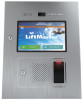
The K41-0117-000 Touchscreen Display and Door Kit is a replacement
for the Connected Access Portal - High Capacity (Models CAPXL and
CAPXLV).
INSTALLATION INSTRUCTIONS
Disconnect and remove control board
1.
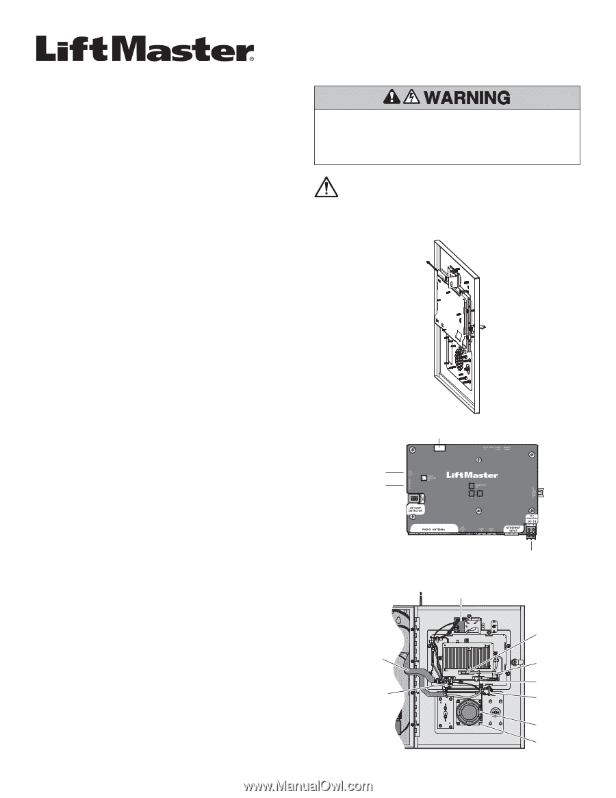
Disconnect power to the CAPXL. Remove the PWR INPUT terminal
block from the Power/Internet Board (Figure B).
2.
Disconnect the USB, Ethernet, computer power, and data cables from
the control board (Figure C).
3.
Cut the cable tie holding the data cable to the control board. Do NOT
cut the data cable.
4.
Remove the 4 locknuts securing the control board to the CAPXL door.
5.
Carefully pull the control board away from the faceplate. Disconnect
the audio cable from the control board. Set aside the control board.
Unplug connectors
6.
Cut the 2 cable ties securing the harness to the left side of the display
bracket. Do NOT cut the cables.
7.
Remove the 2 mounting screws from the light sensor board and allow
the board to dangle by the cables.
8.
Remove the 2 locknuts from the postal lock lever-switch. Remove the
postal lock lever-switch. Remove the plastic spacers.
9.
Disconnect the Touch Panel connector from the Power/Internet board
(Figure B).
10.
Cut the connector off of the Touch Panel harness and slide the
remaining wire entirely through the braided sleeve.
11.
Unplug the backlight connector (Red/White wire) from the Power/
Internet board and pull the wire entirely through the braided sleeve.
Discard the backlight connector.
Remove hardware
12.
Remove the 2 screws securing the microphone to the CAPXL door.
13.
Remove the 4 nuts securing the speaker to the CAPXL door, carefully
pull speaker from door and set inside enclosure.
14.
Remove 1 wingnut securing the postal lock cover or remove 4 nuts
holding postal lock in place (if equipped). Remove postal lock/cover.
15.
Remove 4 locknuts securing card reader bracket in place, remove
card reader (if equipped). Carefully remove reader bracket/cover.
16.
Remove 1 wingnut securing camera bracket in place. Carefully
remove camera/bracket and set inside enclosure.
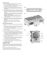
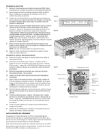
K41-0117-000 Carton Inventory (Figure A):
Fully assembled CAPXL door
with LCD display and touchscreen assembly, display gasket, camera
window, nut 6-32 (9), cable tie (8), installation instructions.
NOTE
: New K001D8439 Power/Internet board will ship in separate box.
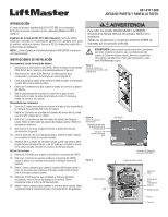
WARNING:
This product can expose you to chemicals including
lead, which are known to the State of California to cause cancer
or birth defects or other reproductive harm. For more information
go to www.P65Warnings.ca.gov.
To prevent possible SERIOUS INJURY or DEATH, disconnect
electric power to operator BEFORE installing.
ALL installations and electrical connections MUST be made by
a qualified individual.
ON
Power/Internet Board
OTS Backlit
PWR INPUT terminal
block location
Touch Panel
connector location
Figure B
Figure A
CAPXL door with LCD display
and touchscreen assembly
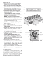
Figure C
Ethernet
Computer
power
Data
cables
Light sensor board
Postal lock
USB
Braided sleeve
Nuts
Speaker
Backlight Power
connector location