Invacare TER Owners Manual - Page 41
Invacare TER Manual
 |
View all Invacare TER manuals
Add to My Manuals
Save this manual to your list of manuals |
Page 41 highlights
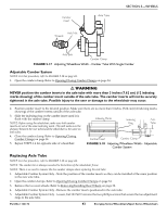
SECTION 5-WHEELS iii. Secure the L‐bracket to base frame in the position shown in Detail "D" with mounting screw, two washers, coved spacer and locknut. Tighten securely. iv. Proceed to STEP 7. 6. Secure the L‐bracket to the COG bracket in the desired mounting position with two mounting screws and locknuts (Detail "B"). Tighten securely. 7. Secure the L‐bracket to the COG bracket in the desired mounting position with two mounting screws and locknuts (Detail "D"). Tighten securely. 8. Repeat STEP 4‐6 for remaining COG bracket. 9. If necessary, install the seat upholstery. Refer to Replacing Adjustable Tension Seat Upholstery on page 50 or Replacing Screw‐On Seat Upholstery. on page 50. DETAIL "A" Seat Rail COG Bracket Mounting Screws L-Bracket COG Bracket DETAIL "B" COG Position 5 COG Position 4 COG Position 3 COG Position 2 COG Position 1 Locknuts L-Bracket Mounting Screws DETAIL "C" DETAIL "D" COG Position 6 COG Position 7 Locknut COG Bracket L-Bracket L-Bracket Washers Mounting Screw Coved Spacer Base Frame Base Frame Mounting Screw, Two Washers, Coved Spacer and Locknut FIGURE 5.15 Adjusting Center of Gravity - Top End Pro Tennis/ Top End Pro BB Part No 1122172 41 Everyday Series Wheelchairs/Sport Series Wheelchairs
-
 1
1 -
2
-
3
-
4
-
5
-
6
-
7
-
8
-
9
-
10
-
11
-
12
-
13
-
14
-
15
-
16
-
17
-
18
-
19
-
20
-
21
-
22
-
23
-
24
-
25
-
26
-
27
-
28
-
29
-
30
-
31
-
32
-
33
-
34
-
35
-
 36
36 -
 37
37 -
 38
38 -
 39
39 -
 40
40 -
 41
41 -
 42
42 -
 43
43 -
 44
44 -
 45
45 -
 46
46 -
47
-
48
-
49
-
50
-
51
-
52
-
53
-
54
-
55
-
56
-
57
-
58
-
59
-
60
-
61
-
62
-
63
-
64
 |
 |
