Invacare TER Owners Manual - Page 26
Terminator Wheelchairs
 |
View all Invacare TER manuals
Add to My Manuals
Save this manual to your list of manuals |
Page 26 highlights
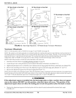
SECTION 4-BACK 95° Back Angle to Seat Rail Back Post Indexing Notch TOP Hex Screw and Locknut Back Angle Bracket Cam 90° Back Angle to Seat Rail Back Post Indexing Notch TOP Hex Screw and Locknut Cam Back Angle Bracket 75° Back Angle to Seat Rail Back Post Indexing Notch Seat Rail 85° Back Angle to Seat Rail Back Post Indexing Notch TOP Hex Screw and Locknut Cam Back Angle Bracket Seat Rail 80° Back Angle to Seat Rail Back Post TOP Hex Screw and Indexing Notch Locknut Cam Back Angle Bracket TOP Hex Screw and Locknut Cam Back Angle Bracket Seat Rail Seat Rail Seat Rail FIGURE 4.2 Back Angle Adjustment - All Models Except Terminator Wheelchairs Terminator Wheelchairs NOTE: For this procedure, refer to FIGURE 4.3 on page 27 and FIGURE 4.4 on page 28. NOTE: The numbers on the back angle plate are intended to define the resulting back angle of a chair that has 2 inch seat drop (at 17 inch depth) and that is measured relative to true vertical with the chair sitting on a level surface. The plus (+) sign increases the back angle and the minus (‐) sign decreases the back angle. The resulting back angle will vary somewhat depending on your chair configuration. Refer to FIGURE 4.4 on page 28 to see these settings converted into back angle relative to the seat. NOTE: Perform this procedure on both sides of the wheelchair at the same time. 1. Fold down the back. Refer to Unfolding/Folding the Back on page 25. 2. Loosen the jam nut on the placement screw located at the bottom of the back cane (Detail "A"). 3. Tighten the placement screw so that the screw and jam nut are snug against the bottom of the back cane (Detail "B"). 4. Remove the mounting screw that secures the adjustment square to the back angle plate (Details "A" and "C"). 5. Remove the adjustment square from the back angle plate (Detail "C"). NOTE: Note the indent on the adjustment square. When the adjustment square is positioned in the back angle plate, the number that is located directly next to the indent will be back angle relative to true vertical. One side of the adjustment square provides back angles of ‐8°, 0° and ‐4°. Flip the adjustment square over to obtain back angles of 8°, 4° and 0° (FIGURE 4.3). ƽ WARNING If the adjustment square is installed into the back angle plate so that a number does not appear next to the indent, DO NOT use this position, otherwise injury will occur. This position of the adjustment square does not allow the locking pins to lock into position when the back is raised. 6. Position the adjustment square in the back plate with the indent located underneath the desired back angle (FIGURE 4.3). Everyday Series Wheelchairs/Sport Series Wheelchairs 26 Part No 1122172
-
 1
1 -
2
-
3
-
4
-
5
-
6
-
7
-
8
-
9
-
10
-
11
-
12
-
13
-
14
-
15
-
16
-
17
-
18
-
19
-
20
-
 21
21 -
 22
22 -
 23
23 -
 24
24 -
 25
25 -
 26
26 -
 27
27 -
 28
28 -
 29
29 -
 30
30 -
 31
31 -
32
-
33
-
34
-
35
-
36
-
37
-
38
-
39
-
40
-
41
-
42
-
43
-
44
-
45
-
46
-
47
-
48
-
49
-
50
-
51
-
52
-
53
-
54
-
55
-
56
-
57
-
58
-
59
-
60
-
61
-
62
-
63
-
64
 |
 |
