Invacare PTBASE Owners Manual - Page 53
Front Riggings
 |
View all Invacare PTBASE manuals
Add to My Manuals
Save this manual to your list of manuals |
Page 53 highlights
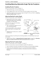
SECTION 7-FRONT RIGGINGS SECTION 7-FRONT RIGGINGS ƽ WARNING After any adjustments, repair or service and before use, make sure that all attaching hardware is tightened securely - otherwise injury or damage may result. While the wheelchair is moving, minimum ground clearance for the front rigging is three inches. If the wheelchair is not moving, the front rigging MUST maintain a minimum of one inch ground clearance - otherwise personal injury and damage may result. For the following procedures, make sure the On/Off switch on the joystick is in the Off position. Installing Adjustable Angle Flip-Up Footplate Hinge NOTE: For this procedure, refer to FIGURE 7.1. 1. Position footplate hinge on the footrest support tube at the desired height. 2. Position mounting screw, washers, spacer, and locknut on the footrest support as shown in FIGURE 7.1. 3. Flip the footplate hinge to the up position. NOTE: The footplate hinge will fall to the down position. 4. Tighten the mounting screw, washer, and locknut that secure the footplate hinge to the footrest support until the footplate hinge remains in the up position. 5. Check the up and down motion of the footplate hinge to make sure the user of the wheelchair can operate the footplates easily. NOTE: If footplate's motion is too tight, loosen the mounting screw and locknut approximately ¼-turn counter clockwise. NOTE: If the footplate's motion is too loose, tighten mounting screw and locknut approximately ¼-turn clockwise. 6. Adjust footplate. Refer to Installing/Adjusting Adjustable Angle Flip-Up Footplates on page 54. Footplate Hinge Mounting Screw Locknut Washers Spacer Footrest Support FIGURE 7.1 Installing Adjustable Angle Flip-Up Footplate Hinge Part No 1134839 53 Power Tiger™
-
 1
1 -
2
-
3
-
4
-
5
-
6
-
7
-
8
-
9
-
10
-
11
-
12
-
13
-
14
-
15
-
16
-
17
-
18
-
19
-
20
-
21
-
22
-
23
-
24
-
25
-
26
-
27
-
28
-
29
-
30
-
31
-
32
-
33
-
34
-
35
-
36
-
37
-
38
-
39
-
40
-
41
-
42
-
43
-
44
-
45
-
46
-
47
-
 48
48 -
 49
49 -
 50
50 -
 51
51 -
 52
52 -
 53
53 -
 54
54 -
 55
55 -
 56
56 -
 57
57 -
 58
58 -
59
-
60
-
61
-
62
-
63
-
64
-
65
-
66
-
67
-
68
-
69
-
70
-
71
-
72
-
73
-
74
-
75
-
76
-
77
-
78
-
79
-
80
-
81
-
82
-
83
-
84
-
85
-
86
-
87
-
88
 |
 |
