Intel BX80570E8200 Mechanical Design Guidelines - Page 111
Appendix G, Mechanical Drawings
 |
UPC - 735858199650
View all Intel BX80570E8200 manuals
Add to My Manuals
Save this manual to your list of manuals |
Page 111 highlights
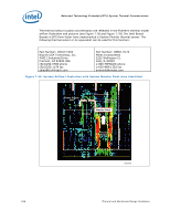
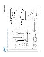
Mechanical Drawings Appendix G Mechanical Drawings The following table lists the mechanical drawings included in this appendix. These drawings refer to the reference thermal mechanical enabling components for the processor. Note: Intel reserves the right to make changes and modifications to the design as necessary. Drawing Description ATX/µATX Motherboard Keep-out Footprint Definition and Height Restrictions for Enabling Components - Sheet 1 ATX/µATX Motherboard Keep-out Footprint Definition and Height Restrictions for Enabling Components - Sheet 2 ATX/µATX Motherboard Keep-out Footprint Definition and Height Restrictions for Enabling Components - Sheet 3 . BTX Thermal Module Keep Out Volumetric - Sheet 1 BTX Thermal Module Keep Out Volumetric - Sheet 2 . BTX Thermal Module Keep Out Volumetric - Sheet 3 BTX Thermal Module Keep Out Volumetric - Sheet 4 BTX Thermal Module Keep Out Volumetric - Sheet 5 ATX Reference Clip - Sheet 1 ATX Reference Clip - Sheet 2 Reference Fastener - Sheet 1 Reference Fastener - Sheet 2 Reference Fastener - Sheet 3 Reference Fastener - Sheet 4 Intel® E18764-001 Reference Solution Assembly Page Number 112 113 114 115 116 117 118 119 120 121 122 123 124 125 126 Thermal and Mechanical Design Guidelines 111
-
 1
1 -
2
-
3
-
4
-
5
-
6
-
7
-
8
-
9
-
10
-
11
-
12
-
13
-
14
-
15
-
16
-
17
-
18
-
19
-
20
-
21
-
22
-
23
-
24
-
25
-
26
-
27
-
28
-
29
-
30
-
31
-
32
-
33
-
34
-
35
-
36
-
37
-
38
-
39
-
40
-
41
-
42
-
43
-
44
-
45
-
46
-
47
-
48
-
49
-
50
-
51
-
52
-
53
-
54
-
55
-
56
-
57
-
58
-
59
-
60
-
61
-
62
-
63
-
64
-
65
-
66
-
67
-
68
-
69
-
70
-
71
-
72
-
73
-
74
-
75
-
76
-
77
-
78
-
79
-
80
-
81
-
82
-
83
-
84
-
85
-
86
-
87
-
88
-
89
-
90
-
91
-
92
-
93
-
94
-
95
-
96
-
97
-
98
-
99
-
100
-
101
-
102
-
103
-
104
-
105
-
 106
106 -
 107
107 -
 108
108 -
 109
109 -
 110
110 -
 111
111 -
 112
112 -
 113
113 -
 114
114 -
 115
115 -
 116
116 -
117
-
118
-
119
-
120
-
121
-
122
-
123
-
124
-
125
-
126
-
127
-
128
 |
 |
