Fujitsu MPB3043AT Product Manual - Page 162
Specification of INITIALIZE DEVICE PARAMETERS command
 |
View all Fujitsu MPB3043AT manuals
Add to My Manuals
Save this manual to your list of manuals |
Page 162 highlights
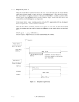
6.2.2 Logical address (1) CHS mode Logical address assignment starts from physical cylinder (PC) 0, physical head (PH) 0, and physical sector (PS) 1 and is assigned by calculating the number of sectors per track which is specified by the INITIALIZE DEVICE PARAMETERS command. The head address is advanced at the subsequent sector from the last sector of the current physical head address. The first physical sector of the subsequent physical sector is the consecutive logical sector from the last sector of the current physical sector. Figure 6.5 shows an example (assuming there is no track skew). Physical sector 12 3 Physical cylinder 0 LS1 Physical head 0 LH0 62 63 64 LS 63 LS1 126 127 LS 63 LS1 LH1 LH2 299 300 LS LS 47 48 LH4 Physical sector 1 Physical cylinder 1 LS 49 Physical head 0 LH4 15 16 LS 63 LS1 78 79 LS 63 LS1 LS2 LH5 LH6 ex: Zone 0 Physical parameter - Physical sector: 1 to 300 Specification of INITIALIZE DEVICE PARAMETERS command - Logical head: LH = 0 to 14 - Logical sector: LS = 1 to 63 Figure 6.5 Address translation (example in CHS mode) C141-E045-02EN 6 - 7
-
 1
1 -
2
-
3
-
4
-
5
-
6
-
7
-
8
-
9
-
10
-
11
-
12
-
13
-
14
-
15
-
16
-
17
-
18
-
19
-
20
-
21
-
22
-
23
-
24
-
25
-
26
-
27
-
28
-
29
-
30
-
31
-
32
-
33
-
34
-
35
-
36
-
37
-
38
-
39
-
40
-
41
-
42
-
43
-
44
-
45
-
46
-
47
-
48
-
49
-
50
-
51
-
52
-
53
-
54
-
55
-
56
-
57
-
58
-
59
-
60
-
61
-
62
-
63
-
64
-
65
-
66
-
67
-
68
-
69
-
70
-
71
-
72
-
73
-
74
-
75
-
76
-
77
-
78
-
79
-
80
-
81
-
82
-
83
-
84
-
85
-
86
-
87
-
88
-
89
-
90
-
91
-
92
-
93
-
94
-
95
-
96
-
97
-
98
-
99
-
100
-
101
-
102
-
103
-
104
-
105
-
106
-
107
-
108
-
109
-
110
-
111
-
112
-
113
-
114
-
115
-
116
-
117
-
118
-
119
-
120
-
121
-
122
-
123
-
124
-
125
-
126
-
127
-
128
-
129
-
130
-
131
-
132
-
133
-
134
-
135
-
136
-
137
-
138
-
139
-
140
-
141
-
142
-
143
-
144
-
145
-
146
-
147
-
148
-
149
-
150
-
151
-
152
-
153
-
154
-
155
-
156
-
 157
157 -
 158
158 -
 159
159 -
 160
160 -
 161
161 -
 162
162 -
 163
163 -
 164
164 -
 165
165 -
 166
166 -
 167
167 -
168
-
169
-
170
-
171
-
172
-
173
-
174
-
175
-
176
-
177
-
178
-
179
-
180
 |
 |
