Dell OptiPlex 5080 Micro Service Manual - Page 43
Optional I/O modules (Type C/ HDMI/VGA/DP/Serial), Serial
 |
View all Dell OptiPlex 5080 manuals
Add to My Manuals
Save this manual to your list of manuals |
Page 43 highlights
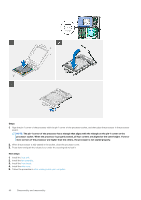
Steps 1. Align and insert the speaker into the slot and press it until the release tab clicks. 2. Connect the speaker cable to the system board. Next steps 1. Install the fan assembly. 2. Install the front bezel. 3. Install the side cover. 4. Follow the procedure in after working inside your computer. Optional I/O modules (Type C/ HDMI/VGA/DP/ Serial) Removing optional I/O modules (Type C/ HDMI/VGA/DP/ Serial) Prerequisites 1. Follow the procedure in before working inside your computer. 2. Remove the side cover. 3. Remove the front bezel. About this task The following images indicate the location of the optional I/O Modules and provide a visual representation of the removal procedure. Steps 1. Remove the two (M3X3) screws that secure the optional i/O module to the computer chassis. 2. Disconnect the I/O-module cable from the connector on the system board. Disassembly and reassembly 43
-
 1
1 -
2
-
3
-
4
-
5
-
6
-
7
-
8
-
9
-
10
-
11
-
12
-
13
-
14
-
15
-
16
-
17
-
18
-
19
-
20
-
21
-
22
-
23
-
24
-
25
-
26
-
27
-
28
-
29
-
30
-
31
-
32
-
33
-
34
-
35
-
36
-
37
-
 38
38 -
 39
39 -
 40
40 -
 41
41 -
 42
42 -
 43
43 -
 44
44 -
 45
45 -
 46
46 -
 47
47 -
 48
48 -
49
-
50
-
51
-
52
-
53
-
54
-
55
-
56
-
57
-
58
 |
 |
