Carvin MX1644 Instruction Manual - Page 23
aciti000
 |
View all Carvin MX1644 manuals
Add to My Manuals
Save this manual to your list of manuals |
Page 23 highlights
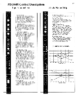
MX1644 Rear Panel 19 9■(1) %emir' z. AGAusional You:ea 0o- 0 itt) 0 0 0 0 0 0 0 0 C 0 0 0 0 0 0 0 0 C 0 C C 0 (0) O O 0 O O O O (g) 0 aciti000 o 1. Line Input Jack The input to the channel line preamp accepts un- balanced signals with levels from -25 dBv up to + 20 dBv 2. Mic Input Connector The snap-in balanced XLR input to the differential mic preamp will accept signal levels up to 0 dBv. 3. Channel Direct Output The channel direct output is taken post fader and post EQ and may be used as a direct input to the multitrack tape recorder, an auxiliary effects send. a cue send, etc 4. Channel Send and Return Jacks These jacks constitute the channel patch point and allow external signal processors to be patched into the channel signal path. The channel patch point is pre fader and post EQ. 5. Sub Output Send and Return Jacks The sub output patch point is pre the output chan- nel fader and allows insertion of external processors into the output channel signal path. 6. Sub Outputs The sub output signals are available on 14/ " phone jacks. The mixer is calibrated at the factory for an output level of +4 dBv for 0 VU indication but can easily be recalibrated to provide an output level of -10 dBv oo at 0 VU indication for use with tape recorders using a -10 dBv operating level. 7. Two-Track Output Jacks The two-track output signals usually feed the two- track tape recorder. For live sound mixing the twotrack outputs are used to feed the main sound system. 8. Mono Output Jacks Balanced and unbalanced mono output signals are provided on two phone jacks and two XLR connectors 9. Stacking Input Jacks Stacking input jacks allow access to each of the sum- ming busses in the mixer. This allows two 1644's to be combined for 32 input channel operation. 10. Graphic EQ Connections Input and output connections are provided for each of the four optional graphic equalizers to allow patching into various signal paths. 11. Monitor Output Jacks The two monitor outputs feed the stage monitors for live sound mixing and feed the headphone cue mix when recording. 12. Control Room Outputs The control room L/R outputs are intended to feed the control room monitor loudspeakers. These outputs also feed the headphone amplifier. 13. Two-Track Input Jacks The output from the two-track recorder is connected to the two-track inputs to allow two-track playback through the system. 14. Effects Return Input Jacks These jacks are used to return signals from reverbs, or other external signal processors. to the output section of the mixer 15. Effects Send Jacks The effects send signals can be sent to external signal processors and returned through the effects return inputs to add effects to the audio. 16. AC Line Fuse The AC line fuse provides protection to both the mixer and the user from improper AC power or other faults 17. Power On/Off Switch This is the main power switch for the mixer. A pilot light built into the switch indicates when power is switched on 18. Power Cord Connector A standard line cord connector allows the power cord to be detached when the mixer is not in use. 19. 120/240V AC Line Selector Switch This restricted access switch allows the MX1688 to be powered from either 120V or 240V AC. MX1644 Technical Specifications Frequency Response Mic or line inputs to two-track output: 15 Hz-25kHz t 1 dB Total Harmonic Distortion Mic in to two-track out 40 dB gain 0 dBv output. 20-20kHz: Line in to two-track out 10 dB gain + 10 dBv output. 20-20kHz: less than .05% less than .02% Equivalent Input Noise unweighted. 150 ohm source: -127 dBv Output Noise All faders minimum: Sub fader at nominal, one channel assigned w/ nominal gain and channel fader settings: -85 dBv -78 dBv Crosstalk Adjacent channels: -60 dB at )kHz Common Mode Rejection Ratio: -70 dB at )kHz Channel Equalizer Type: High band: Hi-Mid band: Mid band: Low band: 4 band fixed frequency t 15 dB 02 10 kHz. shelving t 15 dB @ 2 kHz. peak/dip t 15 dB @ 500 Hz, peak/dip t 15 dB @ 100 Hz. shelving Integrated Circuits: NE5532 ultra-low noise high speed op amps at input and output stages Graphic Equalizers (4): Type: Max Boost/Cut: Center frequencies: 9 band on octave intervals t 15 dB 63.125.250.500.lk.2k.4k.8k.16 kHz Peak Warning Level: 6 dB below clipping ( + 14 dBv) Phantom Power: +48 V DC applied to pins 2 and 3 Mic Input Connector: Input impedance: Source impedance: Nominal input range: Maximum input level: 3-pin XLR type 4.4k ohms (balanced) nominal "low impedance" (50 ohms to 2k ohms) -70 to -10 dBv (.3mV to 300mV) + 10 dBv (3.3 V) Line Input Connector: Input impedance: Nominal input range: Maximum input level: Maximum Gain Mic in to sub out: Line in to sub out: Sub Outputs 1-4 Connector: Nominal output level: Maximum output level: Mono and Two-Track Outputs: Connector: Nominal output level: Maximum output level: (10k ohm load) Mon, Effects. and Control Room Outputs Connector: Nominal output level: Maximum output level: (10k ohm load) Headphone Output Connector: Load impedance: Power Supply: Accessory Mini-Lamp Connector: Power Requirements: Weight: Dimensions: Warranty: 14/ " phone jack 22k ohms (unbalanced) -20 dBv to + 10 dBv (100mV to 3V) + 30 dBv (30V) 74 dB 45 dB 14/ " phone (unbalanced) +4 dBv (can be set up for -10 dBv) +20 dBv (10k ohm load) 3-pin XLR (balanced) and 14/ " phone (unbalanced) +4 dBv +20 dBv 14/ " phone (unbalanced) +4 dBv +20 dBv 1/4" stereo phone jack 8 ohms or higher (stereo) Fully regulated with current limiting BNC type female connector 120V AC. or 240V AC 50 or 60 Hz 70 lbs. 8%"H. 35%"W. 29"D 1 year parts and labor Note: 0 dBv referenced to .775 V RMS All noise measurements are unweighted. 20kHz bandwidth
-
 1
1 -
2
-
3
-
4
-
5
-
6
-
7
-
8
-
9
-
10
-
11
-
12
-
13
-
14
-
15
-
16
-
17
-
 18
18 -
 19
19 -
 20
20 -
 21
21 -
 22
22 -
 23
23 -
 24
24 -
 25
25 -
 26
26 -
 27
27 -
 28
28 -
29
-
30
-
31
-
32
-
33
-
34
-
35
-
36
-
37
-
38
-
39
-
40
-
41
-
42
-
43
-
44
-
45
-
46
-
47
-
48
-
49
-
50
-
51
-
52
-
53
-
54
-
55
-
56
-
57
-
58
-
59
-
60
-
61
-
62
-
63
-
64
-
65
-
66
-
67
-
68
-
69
-
70
-
71
-
72
-
73
-
74
 |
 |
