Carvin MX1644 Instruction Manual - Page 19
MX1644, Control, Descriptions
 |
View all Carvin MX1644 manuals
Add to My Manuals
Save this manual to your list of manuals |
Page 19 highlights
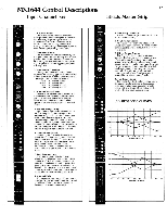
MX1644 Control Descriptions 17 Input Channel X16 Effects Master Strip LMINICE.it GAINsr0 E0 -"NI MIDs" 0 0 °NION °AWN2i0 °'EFF EFF 2 c , 3-4 • L R SOLO C] PEAK 10- - o s 10 20 30 40 50-- 1. Mic/Line Switch This switch is used to select either the microphone or line input signals to the channel. Normally playback signals from the multitrack recorder are connected to line inputs 1 through 4 leaving line inputs 5 through 16 free for high-level signal inputs or even direct Inputs from guitar or bass. 2. Input Gain Control This rotary control simultaneously adjusts the gain of both the mic preamp and the line preamp and is used to set the level of the channel signal. The level should be kept as high as possible without triggering the peak warning LED. 3. Four Band EQ Section The high and low bands of the channel equalizer are shelving type while the mid and hi-mid bands have a peak/dip characteristic. The range of EQ action is as follows: High: ± 15 dB @ 10kHz Hi-Mid: ± 15 dB @ 2kHz Mid: ± 15 dB @ 500 Hz Low: t 15 dB @ 100 Hz 4. Mon and Effects Sends Each channel has two monitor sends and two effects sends. Monitor sends are taken pre fader whereas effects sends are post fader. Effects 1 feeds the internal reverb system but is also available to feed external effects. 5. Pan and Assign Group Input channel signals are assigned to out- put channel pairs by depressing the appropriate assign switches. The channel pan control then pans the signal across the assigned output channels or can be positioned to send the signal to any one output channel. By depressing the L-R assign switch the channel signal is sent directly to the twotrack buss, bypassing the output channels. 6. Channel Solo Switch Depressing the channel solo switch ac- tivates the on FED switching network which silently interrupts the signal to the control room and replaces it with the signal that Is being soloed. When a solo switch is depressed an LED is illuminated at that switch and the master solo LED is illuminated as well. 7. Peak Warning Light The channel peak LED illuminates whenever signal peaks come within 6dB of clipping any stage in the input channel. A peak stretching circuit is used to insure that even momentary overloads are clearly indicated to the operator. The operator should simply lower the channel gain control by one setting when a peak warning is indicated. 8. Channel Fader A professional long throw 100mm fader is provided for precise control over the channel signal level. Fader graphics accurately indicate gain or attenuation settings. 12VLAMP MSAESNTEDRS 4 °MON • • 11U MONO °'EFF EFF2°' EFFRTN A 5 . . / LEVEL • C 1. Mini-Lamp Connector A BNC connector is provided for use with an optional mini-lamp. 2. Send Master Section After each of the mon and effects send signals have been summed, the send master controls set the overall output level for these four signals. 3. Effects Return Groups The A and B effects return groups are identical. Each return group provides a way of returning an effects signal to the mixer, setting the return level, and assigning the effects to output channels, mon 1 and 2, or the two-track output. A pan control is provided to allow panning across the mon or output channels. The internal reverb normally returns through effects A unless a plug is inserted in the effects return A jack. 4. Two-Track Faders The master two-track faders located below the system master strip are a close spaced fader pair to allow easy operation of both faders with one finger. These faders set the level of the two-track output signals. • L R 1-2 *1 3-4 L-R MON1-2 20 EFFREN B .10 Ode EQ RESPONSE CURVES TREBLE MIO °LECVEI2° -2o 20 50 100 200 500 1K 2K FRODUENICY 11.1MERTZ 5K 10K 20PC MON1.2*- .20 SASS SE 10 HI MID Ode -41°1 10 -o -5 - -m 20 50 100 200 500 1K 2K RIEOUBICY N HERTZ -IO - SK XIX 20K -30-40 -50 -
-
 1
1 -
2
-
3
-
4
-
5
-
6
-
7
-
8
-
9
-
10
-
11
-
12
-
13
-
 14
14 -
 15
15 -
 16
16 -
 17
17 -
 18
18 -
 19
19 -
 20
20 -
 21
21 -
 22
22 -
 23
23 -
 24
24 -
25
-
26
-
27
-
28
-
29
-
30
-
31
-
32
-
33
-
34
-
35
-
36
-
37
-
38
-
39
-
40
-
41
-
42
-
43
-
44
-
45
-
46
-
47
-
48
-
49
-
50
-
51
-
52
-
53
-
54
-
55
-
56
-
57
-
58
-
59
-
60
-
61
-
62
-
63
-
64
-
65
-
66
-
67
-
68
-
69
-
70
-
71
-
72
-
73
-
74
 |
 |
