Acer Altos S200F User Manual - Page 47
Installing a SATA Drive Carrier Module 1
 |
View all Acer Altos S200F manuals
Add to My Manuals
Save this manual to your list of manuals |
Page 47 highlights
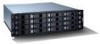
Getting Started 2.11.2 Procedure 1 Important Release the carrier handle, by pressing the latch in the handle towards the right and insert the carrier into the enclosure (Figure 2-13). For a Rack Mounted System: Ensure that the carrier is orientated so that the drive is uppermost and the handle opens from the left. For a Tower System: Ensure that the carrier is orientated so that the carrier lock position is uppermost and the handle opens from the top 2 Slide the carrier, gently, all the way into the enclosure until it is stopped by the camming lever on the right of the carrier (Figure 2-14) 3 Note Cam the carrier home - the camming foot on the base of the carrier will engage into a slot in the enclosure. Continue to push firmly until the handle fully engages. A click should be heard as the latch engages and holds the handle closed (Figure 2-15). Ensure that the Handle always opens from the left. Figure 2-13 Installing a SATA Drive Carrier Module (1) Note Removal is the reverse of this procedure (press on the latch to release the handle). 35
-
 1
1 -
2
-
3
-
4
-
5
-
6
-
7
-
8
-
9
-
10
-
11
-
12
-
13
-
14
-
15
-
16
-
17
-
18
-
19
-
20
-
21
-
22
-
23
-
24
-
25
-
26
-
27
-
28
-
29
-
30
-
31
-
32
-
33
-
34
-
35
-
36
-
37
-
38
-
39
-
40
-
41
-
 42
42 -
 43
43 -
 44
44 -
 45
45 -
 46
46 -
 47
47 -
 48
48 -
 49
49 -
 50
50 -
 51
51 -
 52
52 -
53
-
54
-
55
-
56
-
57
-
58
 |
 |
