Acer Altos S200F User Manual - Page 18
Operators Panel
 |
View all Acer Altos S200F manuals
Add to My Manuals
Save this manual to your list of manuals |
Page 18 highlights
Altos S205F / S200F User's Manual 1.3.2 Operators Panel Supplied as an integral part of the Enclosure core product, a typical Operators (Ops) Panel is shown in Figure 1-8. Figure 1-8 Ops Panel The Ops Panel provides the enclosure with a micro controller which is used to monitor and control all elements of the Enclosure. 1.3.2.1 Ops Panel Indicators and Switches The Ops Panel includes Light Emitting diodes (LEDs) which show the status for all modules, an Audible Alarm which indicates when a fault state is present, a push-button Alarm Mute switch and a thumb wheel SEL_ID Address Range selector switch. The Ops Panel switch functions are shown in Table 1-1 and Table 1-2. 6
-
 1
1 -
2
-
3
-
4
-
5
-
6
-
7
-
8
-
9
-
10
-
11
-
12
-
 13
13 -
 14
14 -
 15
15 -
 16
16 -
 17
17 -
 18
18 -
 19
19 -
 20
20 -
 21
21 -
 22
22 -
 23
23 -
24
-
25
-
26
-
27
-
28
-
29
-
30
-
31
-
32
-
33
-
34
-
35
-
36
-
37
-
38
-
39
-
40
-
41
-
42
-
43
-
44
-
45
-
46
-
47
-
48
-
49
-
50
-
51
-
52
-
53
-
54
-
55
-
56
-
57
-
58
 |
 |

Altos S205F / S200F
User’s Manual
6
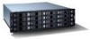
1.3.2
Operators Panel
Supplied as an integral part of the Enclosure core product, a typical Operators (Ops) Panel is shown
in
Figure 1–8
.
The Ops Panel provides the enclosure with a micro controller which is used to monitor and control
all elements of the Enclosure.
1.3.2.1
Ops Panel Indicators and Switches
The Ops Panel includes Light Emitting diodes (LEDs) which show the status for all modules, an
Audible Alarm which indicates when a fault state is present, a push-button Alarm Mute switch and
a thumb wheel SEL_ID Address Range selector switch.
The Ops Panel switch functions are shown in
Table 1–1
and
Table 1–2
.
Figure 1–8
Ops Panel