Acer ARMC_2 User Manual - Page 18
Step 2 Plug in the ARMC/2 Card into the Host System and Atta, JP4 and JP5 Chassis/Motherboard Power Switch, JP6 ARMC/2 Reset Button, JP7 and JP8 Chassis/Motherboard Reset Switch, Step 3 Connect External Cables
 |
View all Acer ARMC_2 manuals
Add to My Manuals
Save this manual to your list of manuals |
Page 18 highlights
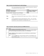
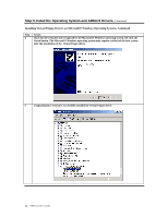
Step 2 Plug in the ARMC/2 Card into the Host System and Attach Internal Cables, Continued JP4 and JP5 Chassis/Motherboard Power Switch JP4 and JP5 can be used in place of the ARMC/2 Universal Cable to power on, power off, and power cycle the motherboard. Connect a two pin cable from the motherboard's Power (Soft On/Off) header to JP4 on your ARMC/2 card. Connect the chassis power switch to JP5 on your ARMC/2 card. Note: JP4 and JP5 can be used in place of the ARMC/2 Universal Cable to power on, power off, and power cycle the motherboard. JP6 ARMC/2 Reset Button You can short this jumper to reset your ARMC/2 card. Pin Description 1 Ground 2 Reset # JP7 and JP8 Chassis/Motherboard Reset Switch JP7 and JP8 can be used in place of the ARMC/2 Universal Cable to reset the motherboard. Connect a two pin cable from the motherboard's Reset header to JP7 on your ARMC/2 card. Connect the chassis reset switch to JP8 on your ARMC/2 card. Note: JP7 and JP8 can be used in place of the ARMC/2 Universal Cable to reset the motherboard. Step 3 Connect External Cables • Connect the USB cable from the back of the ARMC/2 card to the motherboard's USB port. • Connect your VGA monitor to your ARMC/2 card. • Connect the RJ45 LAN cable from your local network to your ARMC/2 card. • Connect your AC adapter. (Only if the AC Adapter is part of your ARMC/2 kit) Cont'd 10 ARMC/2 User's Guide
-
 1
1 -
2
-
3
-
4
-
5
-
6
-
7
-
8
-
9
-
10
-
11
-
12
-
 13
13 -
 14
14 -
 15
15 -
 16
16 -
 17
17 -
 18
18 -
 19
19 -
 20
20 -
 21
21 -
 22
22 -
 23
23 -
24
-
25
-
26
-
27
-
28
-
29
-
30
-
31
-
32
-
33
-
34
-
35
-
36
-
37
-
38
-
39
-
40
-
41
-
42
-
43
-
44
-
45
-
46
-
47
-
48
-
49
-
50
-
51
-
52
-
53
-
54
-
55
-
56
-
57
-
58
-
59
-
60
-
61
-
62
-
63
-
64
-
65
-
66
-
67
-
68
-
69
-
70
-
71
-
72
-
73
-
74
-
75
-
76
-
77
-
78
-
79
-
80
-
81
-
82
-
83
-
84
-
85
-
86
-
87
-
88
-
89
-
90
-
91
-
92
-
93
-
94
-
95
-
96
-
97
-
98
-
99
-
100
-
101
-
102
-
103
-
104
-
105
-
106
-
107
-
108
-
109
-
110
-
111
-
112
-
113
-
114
-
115
-
116
-
117
-
118
-
119
-
120
-
121
-
122
-
123
-
124
-
125
-
126
-
127
-
128
-
129
-
130
-
131
-
132
-
133
-
134
-
135
-
136
-
137
-
138
-
139
-
140
-
141
-
142
-
143
-
144
-
145
-
146
-
147
-
148
-
149
-
150
-
151
-
152
-
153
 |
 |
