2012 Yamaha Motorsports Grizzly 700 4x4 EPS Owners Manual - Page 141
2012 Yamaha Motorsports Grizzly 700 4x4 EPS Manual

Page 141 highlights
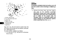
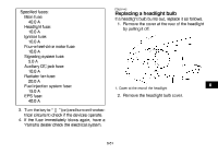
2. Connect the positive battery lead first, then connect the negative battery lead by installing their bolt. NOTICE: When installing the battery, the main switch must be off, and the positive lead must be connected before the negative lead. [ECB01110] Tightening torques: Carrier bolt (top): 34 Nm (3.4 m·kgf, 25 ft·lbf) Carrier bolt (under the fenders): 7 Nm (0.7 m·kgf, 5.1 ft·lbf) 5. Install the panel. 1 EBU30520 Replacing a fuse 2 1. Positive battery lead (red) 2. Negative battery lead (black) 8 3. Install the battery holding plate by installing the nuts. 4. Install the front carrier by installing the bolts and tightening them to the specified torques. 1. 2. 3. 4. 5. Fuse box Main fuse EPS fuse Fuel injection system spare fuse Fuel injection system fuse 8-59
-
 1
1 -
2
-
3
-
4
-
5
-
6
-
7
-
8
-
9
-
10
-
11
-
12
-
13
-
14
-
15
-
16
-
17
-
18
-
19
-
20
-
21
-
22
-
23
-
24
-
25
-
26
-
27
-
28
-
29
-
30
-
31
-
32
-
33
-
34
-
35
-
36
-
37
-
38
-
39
-
40
-
41
-
42
-
43
-
44
-
45
-
46
-
47
-
48
-
49
-
50
-
51
-
52
-
53
-
54
-
55
-
56
-
57
-
58
-
59
-
60
-
61
-
62
-
63
-
64
-
65
-
66
-
67
-
68
-
69
-
70
-
71
-
72
-
73
-
74
-
75
-
76
-
77
-
78
-
79
-
80
-
81
-
82
-
83
-
84
-
85
-
86
-
87
-
88
-
89
-
90
-
91
-
92
-
93
-
94
-
95
-
96
-
97
-
98
-
99
-
100
-
101
-
102
-
103
-
104
-
105
-
106
-
107
-
108
-
109
-
110
-
111
-
112
-
113
-
114
-
115
-
116
-
117
-
118
-
119
-
120
-
121
-
122
-
123
-
124
-
125
-
126
-
127
-
128
-
129
-
130
-
131
-
132
-
133
-
134
-
135
-
 136
136 -
 137
137 -
 138
138 -
 139
139 -
 140
140 -
 141
141 -
 142
142 -
 143
143 -
 144
144 -
 145
145 -
 146
146 -
147
-
148
-
149
-
150
-
151
-
152
-
153
-
154
-
155
-
156
-
157
-
158
-
159
-
160
-
161
-
162
-
163
-
164
-
165
-
166
-
167
-
168
-
169
-
170
-
171
-
172
-
173
-
174
 |
 |
