2012 Yamaha Motorsports FX Nytro M-TX 153 Owners Manual - Page 25
2012 Yamaha Motorsports FX Nytro M-TX 153 Manual

Page 25 highlights
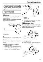
Control functions The drive guard is located behind the left side cover. (See page 52 for removal procedures.) 1 To remove the drive guard 1. Pull out the drive guard locking pin from the drive guard rear holder. 1 2 1. Drive guard 2. 1. Drive guard 2. Drive guard locking pin Align the slots in the rear of the drive guard with the projections on the drive guard rear holder, and then insert the drive guard locking pin into the holder as shown. 2. Lift up the rear of the drive guard as shown, and then pull the guard rearward to remove it. 1 2 1. Drive guard 2. Drive guard locking pin ESU13044 Storage pouch To install the drive guard 1. Fit the front slots in the drive guard over the projections on the drive guard front holder. The storage pouch is located under the shroud. (See page 52 for shroud removal procedures.) Use the storage pouch to store the tool kit, manuals, spare parts, such as the Vbelt, or other small items. 19
-
 1
1 -
2
-
3
-
4
-
5
-
6
-
7
-
8
-
9
-
10
-
11
-
12
-
13
-
14
-
15
-
16
-
17
-
18
-
19
-
 20
20 -
 21
21 -
 22
22 -
 23
23 -
 24
24 -
 25
25 -
 26
26 -
 27
27 -
 28
28 -
 29
29 -
 30
30 -
31
-
32
-
33
-
34
-
35
-
36
-
37
-
38
-
39
-
40
-
41
-
42
-
43
-
44
-
45
-
46
-
47
-
48
-
49
-
50
-
51
-
52
-
53
-
54
-
55
-
56
-
57
-
58
-
59
-
60
-
61
-
62
-
63
-
64
-
65
-
66
-
67
-
68
-
69
-
70
-
71
-
72
-
73
-
74
-
75
-
76
-
77
-
78
-
79
-
80
-
81
-
82
-
83
-
84
-
85
-
86
-
87
-
88
-
89
-
90
-
91
-
92
-
93
-
94
-
95
-
96
-
97
-
98
-
99
-
100
-
101
-
102
-
103
-
104
 |
 |
