2011 Yamaha Motorsports Apex X-TX Owners Manual - Page 36
2011 Yamaha Motorsports Apex X-TX Manual

Page 36 highlights
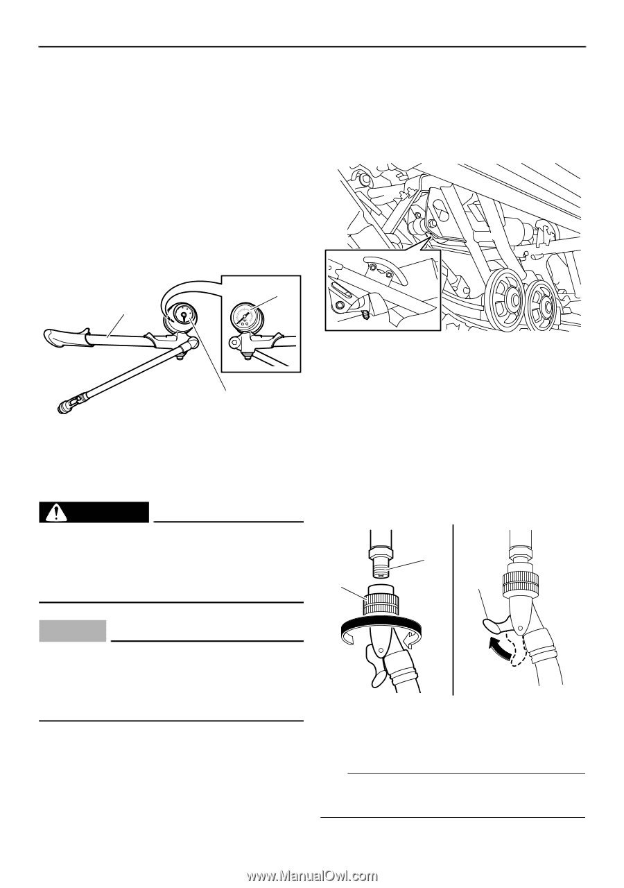
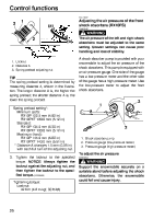
Control functions ESU13831 Adjusting the air pressure of the rear shock absorber (RX10PS) A shock absorber pump is provided with your snowmobile to adjust the air pressure of the shock absorber. This pump is equipped with an air pressure gauge. One side of the gauge has a low-pressure meter and the other side of the gauge has a high-pressure meter. Use the high-pressure meter to adjust the rear shock absorber. 2. 3. Lift the rear of the snowmobile onto a suitable stand to raise the drive track off the ground. Remove the air valve cap from the shock absorber. 1 50 3 150 10 0 20 0 15 10 5 0 RACING SHOX 250 20 30 0 bar psi 1 1. Air valve cap 2 1. Shock absorber pump 2. Pressure gauge (low-pressure meter) 3. Pressure gauge (high-pressure meter) EWS00800 WARNING Support the snowmobile securely on a suitable stand before adjusting the shock absorber. Otherwise, the snowmobile could fall and cause injury. ECS01030 NOTICE Make sure that there is no load on the shock absorber and that it is fully extended before making any air pressure adjustments. To adjust the air pressure 1. Place the snowmobile on a level surface and apply the parking brake. 30 0 4. Install the hose connector of the shock absorber pump onto the air valve of the shock absorber, tighten it approximately six turns until the pressure registers on the pump gauge, and then pull the hose connector lock lever up. NOTICE: Do not overtighten the connector onto the air valve as this will damage the connector seal. [ECS00721] 1 2 3 1. Air valve 2. Hose connector 3. Hose connector lock lever TIP If the shock absorber has no air pressure, the gauge reading will be zero.
-
 1
1 -
2
-
3
-
4
-
5
-
6
-
7
-
8
-
9
-
10
-
11
-
12
-
13
-
14
-
15
-
16
-
17
-
18
-
19
-
20
-
21
-
22
-
23
-
24
-
25
-
26
-
27
-
28
-
29
-
30
-
 31
31 -
 32
32 -
 33
33 -
 34
34 -
 35
35 -
 36
36 -
 37
37 -
 38
38 -
 39
39 -
 40
40 -
 41
41 -
42
-
43
-
44
-
45
-
46
-
47
-
48
-
49
-
50
-
51
-
52
-
53
-
54
-
55
-
56
-
57
-
58
-
59
-
60
-
61
-
62
-
63
-
64
-
65
-
66
-
67
-
68
-
69
-
70
-
71
-
72
-
73
-
74
-
75
-
76
-
77
-
78
-
79
-
80
-
81
-
82
-
83
-
84
-
85
-
86
-
87
-
88
-
89
-
90
-
91
-
92
-
93
-
94
-
95
-
96
-
97
-
98
-
99
-
100
-
101
-
102
-
103
-
104
-
105
-
106
 |
 |