2009 Yamaha Motorsports V Star 250 Owners Manual - Page 26
2009 Yamaha Motorsports V Star 250 Manual

Page 26 highlights
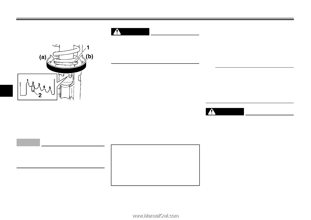
INSTRUMENT AND CONTROL FUNCTIONS EAU14881 EWA10210 EAU15301 Adjusting the shock absorber assemblies WARNING Always adjust both shock absorber assemblies equally, otherwise poor handling and loss of stability may result. Adjust the spring preload as follows. To increase the spring preload and thereby harden the suspension, turn the adjusting ring on each shock absorber assembly in direction (a). To decrease the spring preload and thereby soften the suspension, turn the adjusting ring on each shock absorber assembly in direction (b). Align the appropriate notch in the adjusting ring with the position indicator on the shock absorber. Spring preload setting: Minimum (soft): 1 Standard: 2 Maximum (hard): 5 Sidestand The sidestand is located on the left side of the frame. Raise the sidestand or lower it with your foot while holding the vehicle upright. TIP The built-in sidestand switch is part of the ignition circuit cut-off system, which cuts the ignition in certain situations. (See further down for an explanation of the ignition circuit cut-off system.) EWA10240 4 1. Spring preload adjusting ring 2. Position indicator WARNING The vehicle must not be ridden with the sidestand down, or if the sidestand cannot be properly moved up (or does not stay up), otherwise the sidestand could contact the ground and distract the operator, resulting in a possible loss of control. Yamaha's ignition circuit cut-off system has been designed to assist the operator in fulfilling the responsibility of raising the sidestand before starting off. Therefore, check this system regularly as described Each shock absorber assembly is equipped with a spring preload adjusting ring. ECA10101 NOTICE To avoid damaging the mechanism, do not attempt to turn beyond the maximum or minimum settings. 4-10
-
 1
1 -
2
-
3
-
4
-
5
-
6
-
7
-
8
-
9
-
10
-
11
-
12
-
13
-
14
-
15
-
16
-
17
-
18
-
19
-
20
-
 21
21 -
 22
22 -
 23
23 -
 24
24 -
 25
25 -
 26
26 -
 27
27 -
 28
28 -
 29
29 -
 30
30 -
 31
31 -
32
-
33
-
34
-
35
-
36
-
37
-
38
-
39
-
40
-
41
-
42
-
43
-
44
-
45
-
46
-
47
-
48
-
49
-
50
-
51
-
52
-
53
-
54
-
55
-
56
-
57
-
58
-
59
-
60
-
61
-
62
-
63
-
64
-
65
-
66
-
67
-
68
-
69
-
70
-
71
-
72
-
73
-
74
-
75
-
76
-
77
-
78
-
79
-
80
-
81
-
82
-
83
-
84
-
85
-
86
-
87
-
88
-
89
-
90
-
91
-
92
-
93
-
94
 |
 |