2008 Yamaha Motorsports Grizzly 350 Auto. 4x4 IRS Owners Manual - Page 30
2008 Yamaha Motorsports Grizzly 350 Auto. 4x4 IRS Manual

Page 30 highlights
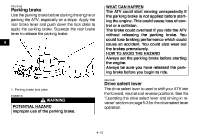
2. To increase the maximum engine power available and the maximum speed of the ATV, turn the adjusting screw in direction (a). To decrease the maximum engine power available and the maximum speed of the ATV, turn the adjusting screw in direction (b). 4 WHAT CAN HAPPEN The throttle cable could be damaged. Improper throttle operation could result. You could lose control, have an accident or be injured. HOW TO AVOID THE HAZARD Do not turn the adjusting screw out more than 12 mm (0.47 in). Always make sure the throttle lever free play is adjusted to 3.0-5.0 mm (0.12-0.20 in). (See page 8-28.) EBU18391 Front brake lever The front brake lever is located on the right handlebar. To apply the front brake, pull the brake lever toward the handlebar grip. 1. Locknut 2. Adjusting screw 3. No more than 12 mm (0.47 in) 3. Tighten the locknut. EWB00190 WARNING POTENTIAL HAZARD Improper adjustment of the speed limiter and throttle. 4-11
-
 1
1 -
2
-
3
-
4
-
5
-
6
-
7
-
8
-
9
-
10
-
11
-
12
-
13
-
14
-
15
-
16
-
17
-
18
-
19
-
20
-
21
-
22
-
23
-
24
-
 25
25 -
 26
26 -
 27
27 -
 28
28 -
 29
29 -
 30
30 -
 31
31 -
 32
32 -
 33
33 -
 34
34 -
 35
35 -
36
-
37
-
38
-
39
-
40
-
41
-
42
-
43
-
44
-
45
-
46
-
47
-
48
-
49
-
50
-
51
-
52
-
53
-
54
-
55
-
56
-
57
-
58
-
59
-
60
-
61
-
62
-
63
-
64
-
65
-
66
-
67
-
68
-
69
-
70
-
71
-
72
-
73
-
74
-
75
-
76
-
77
-
78
-
79
-
80
-
81
-
82
-
83
-
84
-
85
-
86
-
87
-
88
-
89
-
90
-
91
-
92
-
93
-
94
-
95
-
96
-
97
-
98
-
99
-
100
-
101
-
102
-
103
-
104
-
105
-
106
-
107
-
108
-
109
-
110
-
111
-
112
-
113
-
114
-
115
-
116
-
117
-
118
-
119
-
120
-
121
-
122
-
123
-
124
-
125
-
126
-
127
-
128
-
129
-
130
-
131
-
132
-
133
-
134
-
135
-
136
-
137
-
138
-
139
-
140
-
141
-
142
-
143
-
144
-
145
-
146
-
147
-
148
-
149
-
150
-
151
-
152
-
153
-
154
-
155
-
156
-
157
-
158
-
159
-
160
-
161
-
162
-
163
-
164
 |
 |
