2007 Yamaha Motorsports Nytro Owners Manual - Page 77
2007 Yamaha Motorsports Nytro Manual

Page 77 highlights
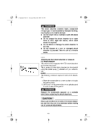
E_8gg.book Page 22 Thursday, March 16, 2006 4:23 PM 3. Remove the air valve cap 2 from the shock absorber. 4. Install the hose connector 3 of the special pump onto the air valve of the shock absorber and tighten it approximately six turns until the pressure registers on the pump gauge. CAUTION: @ Do not overtighten the connector onto the air valve as this will damage the connector seal. @ NOTE: @ If the shock absorber has no air pressure, the gauge reading will be zero. @ 5. To increase the air pressure, operate the pump a few times. The pressure should increase slowly. If the pressure increases rapidly, check to make sure that the pump is properly connected and tightened onto the air valve. To decrease the air pressure, push the black bleed valve button 4. NOTE: @ To allow pressure to escape from the pump and the shock absorber, push the button halfway down and hold it. To allow only a small amount of pressure to escape, push the button all the way down and quickly release it. @ 6. Remove the hose connector from the air valve. NOTE: @ When removing the connector, the sound of air escaping may be heard, but this is from the pump hose, not the shock absorber. @ Air pressure range: 345 kPa (3.4 kgf/cm2, 50 psi) to 1,034 kPa (10.3 kgf/cm2, 150 psi) Recommended air pressure: 483 kPa (4.8 kgf/cm2, 70 psi) 8-22
-
 1
1 -
2
-
3
-
4
-
5
-
6
-
7
-
8
-
9
-
10
-
11
-
12
-
13
-
14
-
15
-
16
-
17
-
18
-
19
-
20
-
21
-
22
-
23
-
24
-
25
-
26
-
27
-
28
-
29
-
30
-
31
-
32
-
33
-
34
-
35
-
36
-
37
-
38
-
39
-
40
-
41
-
42
-
43
-
44
-
45
-
46
-
47
-
48
-
49
-
50
-
51
-
52
-
53
-
54
-
55
-
56
-
57
-
58
-
59
-
60
-
61
-
62
-
63
-
64
-
65
-
66
-
67
-
68
-
69
-
70
-
71
-
 72
72 -
 73
73 -
 74
74 -
 75
75 -
 76
76 -
 77
77 -
 78
78 -
 79
79 -
 80
80 -
 81
81 -
 82
82 -
83
-
84
-
85
-
86
-
87
-
88
-
89
-
90
-
91
-
92
-
93
-
94
-
95
-
96
-
97
-
98
-
99
-
100
-
101
-
102
-
103
-
104
-
105
-
106
-
107
-
108
-
109
-
110
 |
 |
