2007 Yamaha Motorsports Apex Owners Manual - Page 73
2007 Yamaha Motorsports Apex Manual

Page 73 highlights
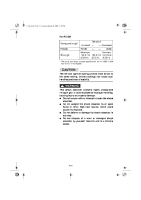
E_8fp.book Page 18 Tuesday, March 28, 2006 4:35 PM 7. If the position is incorrect, adjust the V-belt position by removing or adding a spacer 4 on each adjusting bolt 5. CD-06E V-belt position More than 1.5 mm (0.06 in) above the edge From 1.5 mm (0.06 in) above the edge to 0.5 mm (0.02 in) below the edge More than 0.5 mm (0.02 in) below the edge Adjustment Remove spacer Not necessary (It is correct.) Add spacer 8. Tighten the adjusting bolts. Adjusting bolt tightening torque: 10 Nm (1.0 m·kgf, 7.2 ft·lb) 9. Install the V-belt over the primary sheave assembly. 10. Rotate the secondary sliding sheave clockwise 6 and push 7 it so that it separates from the secondary fixed sheave. 11. Install the V-belt 8 between the secondary sliding and fixed sheaves. 12. Install the drive guard. 13. Install the left side cover and the shroud. WARNING @ Never run the engine with the V-belt or drive guard removed. @ 8-18
-
 1
1 -
2
-
3
-
4
-
5
-
6
-
7
-
8
-
9
-
10
-
11
-
12
-
13
-
14
-
15
-
16
-
17
-
18
-
19
-
20
-
21
-
22
-
23
-
24
-
25
-
26
-
27
-
28
-
29
-
30
-
31
-
32
-
33
-
34
-
35
-
36
-
37
-
38
-
39
-
40
-
41
-
42
-
43
-
44
-
45
-
46
-
47
-
48
-
49
-
50
-
51
-
52
-
53
-
54
-
55
-
56
-
57
-
58
-
59
-
60
-
61
-
62
-
63
-
64
-
65
-
66
-
67
-
 68
68 -
 69
69 -
 70
70 -
 71
71 -
 72
72 -
 73
73 -
 74
74 -
 75
75 -
 76
76 -
 77
77 -
 78
78 -
79
-
80
-
81
-
82
-
83
-
84
-
85
-
86
-
87
-
88
-
89
-
90
-
91
-
92
-
93
-
94
-
95
-
96
-
97
-
98
-
99
-
100
-
101
-
102
-
103
-
104
-
105
-
106
-
107
-
108
 |
 |
