2007 Yamaha Motorsports Apex RTX Owners Manual - Page 87
2007 Yamaha Motorsports Apex RTX Manual

Page 87 highlights
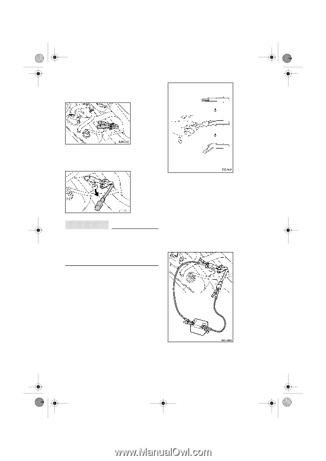
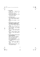
E_8gt.book Page 2 Tuesday, March 28, 2006 5:37 PM 2. Remove the shroud and the right side cover. (See pages 8-5-8-7 for removal procedures.) 3. Remove the red (+) connecting lead from the lead holder and move it away from the black (-) connecting lead. 5. Connect the other end of the red (+) jumper cable to the positive (+) terminal of the booster battery. 6. Connect the black (-) jumper cable to the negative (-) terminal of the booster battery. 7. Pull the black (-) connecting lead cover to expose the terminal through the slit in the cover, and then connect the black (-) jumper cable to the black (-) connecting lead. CAUTION: @ Be sure to connect the red (+) jumper cable to the red (+) connecting lead and the black (-) jumper cable to the black (-) connecting lead. Do not reverse the connections. @ 4. Pull the red (+) connecting lead cover to expose the terminal through the slit in the cover, and then connect the red (+) jumper cable to the red (+) connecting lead. 9-2
-
 1
1 -
2
-
3
-
4
-
5
-
6
-
7
-
8
-
9
-
10
-
11
-
12
-
13
-
14
-
15
-
16
-
17
-
18
-
19
-
20
-
21
-
22
-
23
-
24
-
25
-
26
-
27
-
28
-
29
-
30
-
31
-
32
-
33
-
34
-
35
-
36
-
37
-
38
-
39
-
40
-
41
-
42
-
43
-
44
-
45
-
46
-
47
-
48
-
49
-
50
-
51
-
52
-
53
-
54
-
55
-
56
-
57
-
58
-
59
-
60
-
61
-
62
-
63
-
64
-
65
-
66
-
67
-
68
-
69
-
70
-
71
-
72
-
73
-
74
-
75
-
76
-
77
-
78
-
79
-
80
-
81
-
 82
82 -
 83
83 -
 84
84 -
 85
85 -
 86
86 -
 87
87 -
 88
88 -
 89
89 -
 90
90 -
 91
91 -
 92
92 -
93
-
94
-
95
-
96
-
97
-
98
-
99
-
100
 |
 |