2003 Yamaha Motorsports V Star Custom Owners Manual - Page 91
2003 Yamaha Motorsports V Star Custom Manual

Page 91 highlights
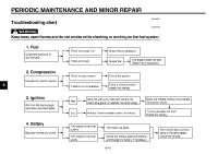
PERIODIC MAINTENANCE AND MINOR REPAIR 3. Install the brake rod onto the brake camshaft lever, and then install the brake pedal free play adjusting nut onto the brake rod. 4. Install the brake torque rod bolt at the brake shoe plate. 5. Install the panel. 6. Lower the rear wheel so that it is on the ground. 7. Tighten the axle nut, the final gear case bolts and the brake torque rod bolt to the specified torques. Tightening torques: Axle nut: 92 Nm (9.2 m·kgf, 67 ft·lbf) Final gear case bolt: 74 Nm (7.4 m·kgf, 54 ft·lbf) Brake torque rod bolt: 20 Nm (2.0 m·kgf, 14 ft·lbf) 8. Adjust the brake pedal free play. (See page 6-23 for brake pedal free play adjustment procedures.) 1. Bolt (× 4) 2. Final gear case 1. Middle gear universal joint 2. Drive shaft EAU04353 6 6. Remove the bolts that secure the final gear case to the swingarm. 7. Lift the rear wheel off the ground according to the procedure on page 6-36. 8. While supporting the drive shaft, pull the rear wheel back to remove the following parts as an assembly: wheel, wheel axle, final gear case, and drive shaft. NOTE: Make sure to support the drive shaft as it is being pulled out. @ @ To install the rear wheel 1. Install the rear wheel, wheel axle, final gear case, and drive shaft by pushing the wheel forward and guiding the drive shaft into the middle gear universal joint. 2. Install the final gear case bolts. 6-39
-
 1
1 -
2
-
3
-
4
-
5
-
6
-
7
-
8
-
9
-
10
-
11
-
12
-
13
-
14
-
15
-
16
-
17
-
18
-
19
-
20
-
21
-
22
-
23
-
24
-
25
-
26
-
27
-
28
-
29
-
30
-
31
-
32
-
33
-
34
-
35
-
36
-
37
-
38
-
39
-
40
-
41
-
42
-
43
-
44
-
45
-
46
-
47
-
48
-
49
-
50
-
51
-
52
-
53
-
54
-
55
-
56
-
57
-
58
-
59
-
60
-
61
-
62
-
63
-
64
-
65
-
66
-
67
-
68
-
69
-
70
-
71
-
72
-
73
-
74
-
75
-
76
-
77
-
78
-
79
-
80
-
81
-
82
-
83
-
84
-
85
-
 86
86 -
 87
87 -
 88
88 -
 89
89 -
 90
90 -
 91
91 -
 92
92 -
 93
93 -
 94
94 -
 95
95 -
 96
96 -
97
-
98
-
99
-
100
-
101
-
102
-
103
-
104
-
105
-
106
-
107
-
108
-
109
-
110
-
111
-
112
-
113
-
114
-
115
-
116
-
117
-
118
-
119
 |
 |
