2003 Yamaha Motorsports V Star Custom Owners Manual - Page 38
2003 Yamaha Motorsports V Star Custom Manual

Page 38 highlights
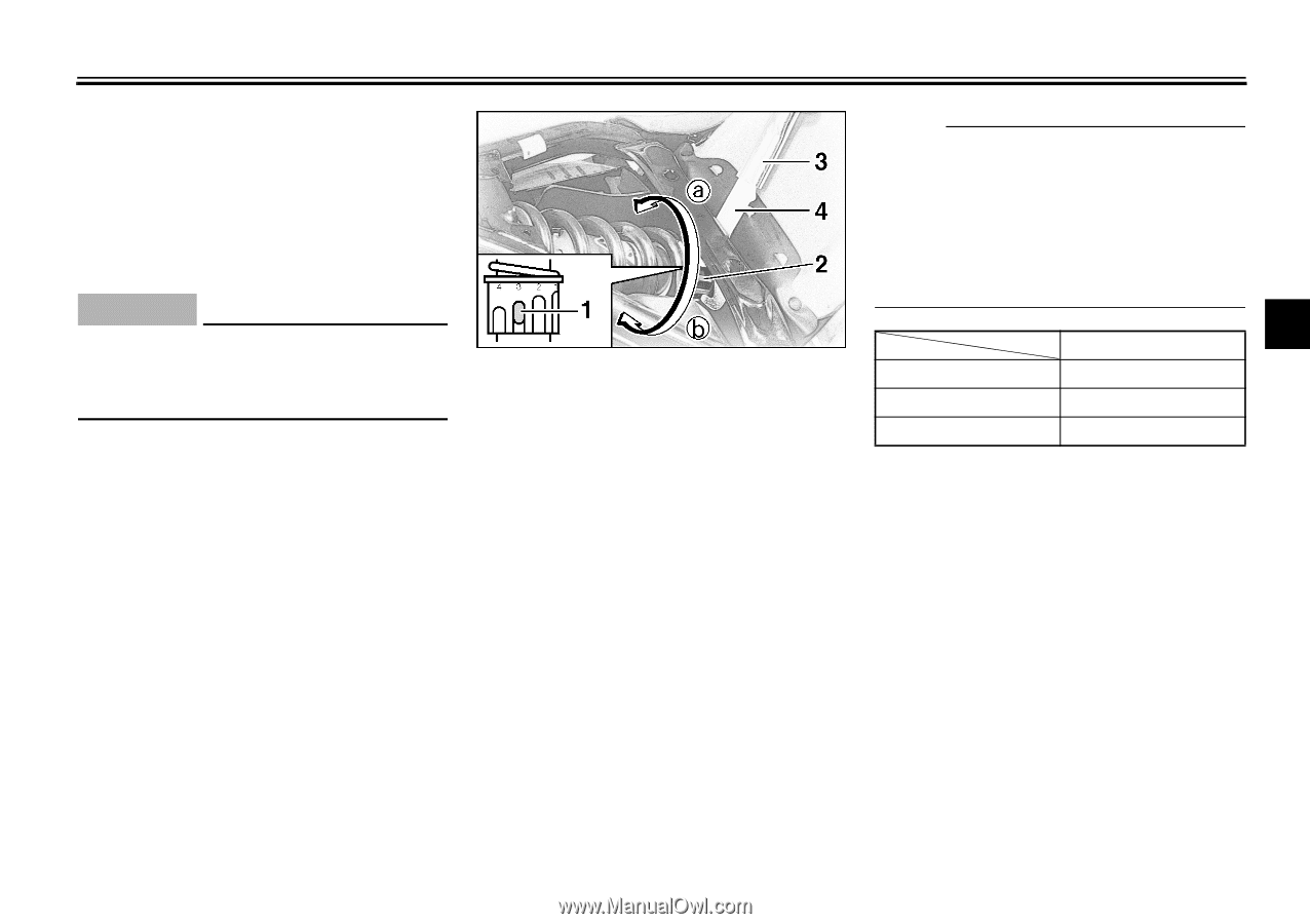
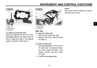
INSTRUMENT AND CONTROL FUNCTIONS EAU00299 Adjusting the shock absorber assembly This shock absorber assembly is equipped with a spring preload adjusting ring. EC000015 NOTE: G Align the appropriate notch in the adjusting ring with the position indicator on the shock absorber. G Use the special wrench and extension bar included in the owner's tool kit to make the adjustment. @ @ CAUTION: Never attempt to turn an adjusting mechanism beyond the maximum or minimum settings. @ @ CI-10E 3 Setting Minimum (soft) Standard 1 3 7 1. 2. 3. 4. Position indicator Spring preload adjusting ring Extension bar Special wrench Maximum (hard) Adjust the spring preload as follows. 1. Remove the passenger and rider seats. (See page 3-9 [XVS650] or 3-11 [XVS650A] for removal and installation procedures.) 2. To increase the spring preload and thereby harden the suspension, turn the adjusting ring in direction a. To decrease the spring preload and thereby soften the suspension, turn the adjusting ring in direction b. 3. Install the passenger and rider seats. 3-14
-
 1
1 -
2
-
3
-
4
-
5
-
6
-
7
-
8
-
9
-
10
-
11
-
12
-
13
-
14
-
15
-
16
-
17
-
18
-
19
-
20
-
21
-
22
-
23
-
24
-
25
-
26
-
27
-
28
-
29
-
30
-
31
-
32
-
 33
33 -
 34
34 -
 35
35 -
 36
36 -
 37
37 -
 38
38 -
 39
39 -
 40
40 -
 41
41 -
 42
42 -
 43
43 -
44
-
45
-
46
-
47
-
48
-
49
-
50
-
51
-
52
-
53
-
54
-
55
-
56
-
57
-
58
-
59
-
60
-
61
-
62
-
63
-
64
-
65
-
66
-
67
-
68
-
69
-
70
-
71
-
72
-
73
-
74
-
75
-
76
-
77
-
78
-
79
-
80
-
81
-
82
-
83
-
84
-
85
-
86
-
87
-
88
-
89
-
90
-
91
-
92
-
93
-
94
-
95
-
96
-
97
-
98
-
99
-
100
-
101
-
102
-
103
-
104
-
105
-
106
-
107
-
108
-
109
-
110
-
111
-
112
-
113
-
114
-
115
-
116
-
117
-
118
-
119
 |
 |