URC MRX-20 Owners Manual - Page 35
Optimizing IR Flasher Levels, RS-232 Connection, Using Sensors with the MRX-20
 |
View all URC MRX-20 manuals
Add to My Manuals
Save this manual to your list of manuals |
Page 35 highlights
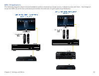
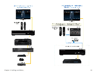
Optimizing IR Flasher Levels Test a few commands for each device before fixing the flasher in place on the front panel of a device. Since Satellite Receivers and Cable Boxes are extremely sensitive to IR overload or saturation, you should test them thoroughly. Put up the cable or satellite on-screen guide and test the navigation arrows. Compare operation via RF to the original remote control. Operation should be identical. If operation is inconsistent or sluggish, lower the IR line output and/or reposition the flasher. If you still have sluggish operation, check that the remote control is set to a particular LINE OUT, rather than ALL. When IR commands are sent to all the flashers in a cabinet, you can have difficulty adjusting the IR Output. Reprogram the remote control to send IR commands only via a specific (1-8) Line Output, then readjust the IR Line Output level. 1. Connect an IR emitter to each IR output and run the emitter wire to the front panel of each component. DO NOT STICK the emitter in place. Adjust the level first. 2. Adjust each of the IR Output levels with the included adjustment tool for best operation. If the component operates best at minimum level, but is still operating sluggishly or intermittently, move the emitter farther away from the component's IR sensor. RS-232 Connection The MRX-20 can operate equipment via RS-232 communication. This allows discrete serial commands to be triggered from a Total Control remote and sent from the MRX-20 over the network connection. The signal is then sent to the device over proprietary URC RS-232 cables. These use either male or female DB-9 connections with standard pin-outs. Programming is done in the Accelerator software. Using Sensors with the MRX-20 The MRX-20 can use either a Video (composite) or Voltage signal to determine the power status of the equipment it controls. This can then be used to alter the function of a Macro by using IF/ELSE statements in the programming software. Using a VID-1 Video Sensor cable, the MRX-20 can detect a video signal from a Composite or Component video output. The VS-100 Voltage Sensor will detect a Voltage of 3-25V either AC or DC. Wiring to the Relay on the MRX-20 The MRX-20 has a Relay with three contacts, NO, NC, and COM. These can be used as dry contacts or to send a current to an electrical switch or motor for use with screens, blinds, curtains, etc. The Relay can be used as either a latching contact or a momentary contact depending on the programming. The command to actuate the Relay is programmed using the Accelerator software and is sent from the MRX-20 when triggered by any Total Control system remote. Chapter 3: Settings and More... 31
-
 1
1 -
2
-
3
-
4
-
5
-
6
-
7
-
8
-
9
-
10
-
11
-
12
-
13
-
14
-
15
-
16
-
17
-
18
-
19
-
20
-
21
-
22
-
23
-
24
-
25
-
26
-
27
-
28
-
29
-
 30
30 -
 31
31 -
 32
32 -
 33
33 -
 34
34 -
 35
35 -
 36
36 -
 37
37 -
 38
38 -
 39
39 -
 40
40 -
41
-
42
-
43
-
44
-
45
 |
 |
