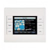
URC KP-4000C Owners Manual
URC KP-4000C Manual
 |
View all URC KP-4000C manuals
Add to My Manuals
Save this manual to your list of manuals |
URC KP-4000C manual content summary:
- URC KP-4000C | Owners Manual - Page 1
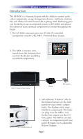
KP-4000 Installation Manual Network Keypad - URC KP-4000C | Owners Manual - Page 2
KP-4000 Installation Manual ©2010 Universal Remote Control, Inc. The information in this manual is copyright protected. No part of this manual may be copied or reproduced in any form without prior written consent from Universal Remote Control, Inc. UNIVERSAL REMOTE CONTROL, INC. SHALL NOT BE LIABLE - URC KP-4000C | Owners Manual - Page 3
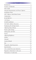
TABLE OF CONTENTS Introduction 1 Features and Benefits 2 Parts Guide 2 Network Requirements and Power Options 3 Installation Notes 5 MAC Address Labels/Reset Button 5 Connections 5 IR OUT/RFTX-1 6 12V Power 7 In-Wall Installation 8 CCP MAC Address Discovery 9 - URC KP-4000C | Owners Manual - Page 4
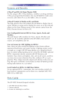
whole house URC Lighting. MAC addressing gives you the ability to use an unlimited amount of KP-4000's and allows the control of many identical components as needed throughout the house. 1. The KP-4000 communicates over IP with IP controlled components and the URC MRX-1 Network Base Station. 2. The - URC KP-4000C | Owners Manual - Page 5
optional RFTX-1 transmitter, low cost wireless control of a local stack of components can be done via a standard MSC-400, MRF-350 or MRF-260. Parts Guide The KP-4000 Network Keypad includes: 1 - KP-4000 Network Base Station 1 - Owner's Manual 4 - Screws for mounting to a wall box Page 2 - URC KP-4000C | Owners Manual - Page 6
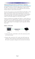
enjoy internet features such as RSS feeds, the Local Area Network must be connected to the Internet. You have three options to power the KP-4000. The KP-4000 is a PoE (power over ethernet) device and can be powered as shown by either a PoE switch or a PoE injector (PoE injectors may be - URC KP-4000C | Owners Manual - Page 7
(not included) Router 1. Connect the CAT 5 cable (RJ45) to the LAN connection on the rear of the KP-4000. 2. Plug the other end of the CAT 5 cable to the PoE Injector which will power the KP-4000. 3. Connect the PoE injector (not included) to the Router. Option 3: No PoE: 12 Volt Power - URC KP-4000C | Owners Manual - Page 8
Base or a wired emitter is needed) 12V Power (not required in a PoE installation) In most installations, you will power the KP-4000 via a single CAT 5 cable connected to the network. The KP-4000 is PoE, so you can power it from either a PoE power injector or any PoE switch. LAN PoE RJ - URC KP-4000C | Owners Manual - Page 9
wire which is connected to the ring of the 3.5mm plug IR Emitter Connection Should you need to drive an IR emitter directly from the KP-4000, you connect the emitter to Data and GND. A URC emitter is wired with a cable that has a silver and a copper conductor. If you have another - URC KP-4000C | Owners Manual - Page 10
a wall adapter in an installation where PoE is not available. You must run an additional two conductor cable to the KP-4000 to utilize this feature. Connect a spliced power adapter 12Volt, 1AMP with the polarity (Positive & Negative) connected correctly. + - 12V 1A - Connect to the + conductor - URC KP-4000C | Owners Manual - Page 11
retro fit box (not included) into the wall. 2. Make connections for IR Out/RFTX-1, LAN, or Power Supply. For connections, refer to page 5. 3. Next, secure KP-4000 onto p-ring or retro fit box with the 4 included screws. 4. Finally attach the magnetic cover plate to the four screws secured into the - URC KP-4000C | Owners Manual - Page 12
the Network Information field, press the Discover button to select the unique MAC address of your unit. 6. The Discover window opens to reveal KP-4000's connected to the network. Highlight the MAC address which matches the KP4000's label. Then press Apply. 7. Begin programming your customer's file - URC KP-4000C | Owners Manual - Page 13
do not press any button on the SETTINGS screen within 1 minute, the KP-4000 will time out and automatically return to normal operation. Adjusting Sleep turn off the LED lighting behind the buttons. Setting Date and Time Your KP-4000 may have been programmed to display the date or time on the - URC KP-4000C | Owners Manual - Page 14
-4000 NETWORK KEYPAD Your KP-4000 may have been programmed to make sounds. This is KP-4000's operating system, memory etc. Network The Network screen displays network information about your KP-4000 and the network it is connect to. Factory Default WARNING! Only use this button when instructed - URC KP-4000C | Owners Manual - Page 15
KP-4000 NETWORK KEYPAD Support. It resets the memory of the KP-4000 to the factory condition. All your programming will be lost! Exit When you have finished adjusting Settings, simply tap the EXIT button to return to normal operation. Page 12 - URC KP-4000C | Owners Manual - Page 16
KP-4000 NETWORK KEYPAD USA Limited Warranty Statement 1. LIMITED WARRANTY AND DISCLAIMERS Universal Remote Control, Inc. ("URC") warrants that URC equipment purchased directly from URC or - URC KP-4000C | Owners Manual - Page 17
contract or other verifiable proof of purchase is required. For the URC equipment support and other important information, please visit URC's website available at www.universalremote.com or call the Customer Service Center at (914) 835-4484. This limited warranty only covers the URC equipment issues - URC KP-4000C | Owners Manual - Page 18
KP-4000 NETWORK KEYPAD our Total Control® whole-house equipment online means buying equipment that does not have URC's limited warranty. Such equipment is not eligible for URC tech support or software support to control my URC Lighting Dimmer/Switch with the KP-4000. Now what? Make sure the RF switch - URC KP-4000C | Owners Manual - Page 19
the button and reset the unit. How do I erase a KP-4000? Press and hold Main + Mute for 3 seconds then select the Factory Default button. Specifications Microprocessor: 190MHz RISC Memory: 128MB Flash Devices: Supports up to 255 Devices Pages: Supports up to 255 Pages on each Device Macro Capability - URC KP-4000C | Owners Manual - Page 20
KP-4000 NETWORK KEYPAD Federal Communication Commission Interference Statement This equipment has been radiate radio frequency energy and, if not installed and used in accordance with the instructions, may cause harmful interference to radio communications. However, there is no guarantee that - URC KP-4000C | Owners Manual - Page 21
KP-4000 NETWORK KEYPAD Regulatory Information to the user CE conformity Notice EN-61000-3-2, 3 Declaration of Conformity "Hereby, Universal Remote Control Inc. declares that this KP-4000 is in compliance with the Essential requirements and other relevant provisions of EMC Directive 2004/108/EC - URC KP-4000C | Owners Manual - Page 22
KP-4000 NETWORK KEYPAD Declaration of Conformity Company Name Company Address Contact Info rmation : (914)835-4484 Fax: (914)835-4532 : UNIVERSAL remote control : Network Key pad : KP-4000 This product herewith complies with the requirements of EMC Directive (2004/108/EC) issued bythe Commission - URC KP-4000C | Owners Manual - Page 23
KP-4000 NETWORK KEYPAD Page 20 - URC KP-4000C | Owners Manual - Page 24
500 Mamaroneck Avenue, Harrison, NY 10528 Phone: (914) 835-4484 Fax: (914) 835-4532 www.universalremote.com OCE-0080A Rev.04_RH
-
 1
1 -
 2
2 -
 3
3 -
 4
4 -
 5
5 -
 6
6 -
 7
7 -
8
-
9
-
10
-
11
-
12
-
13
-
14
-
15
-
16
-
17
-
18
-
19
-
20
-
21
-
22
-
23
-
24
 |
 |
KP-4000 Installation Manual
Network Keypad