Sharp XV-Z200U XVZ200U Operation Manual - Page 10
Projector Rear View - remote
 |
UPC - 074000364028
View all Sharp XV-Z200U manuals
Add to My Manuals
Save this manual to your list of manuals |
Page 10 highlights
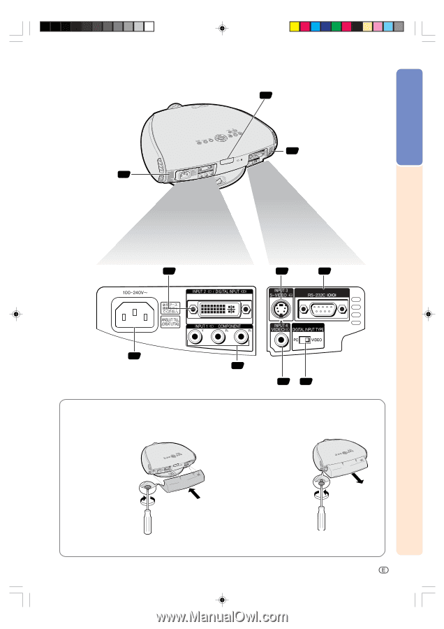
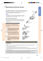
Introduction Projector (Rear View) Remote control sensor 11 Intake ventilative hole 62 62 Intake ventilative hole INPUT 2/DIGITAL INPUT 18 terminal INPUT 3 S-VIDEO terminal 15 (4-pin Mini DIN) 23 RS-232C terminal (9-pin D-sub) 14 AC socket INPUT 1 COMPONENT 17 terminals (RCA) INPUT 4 VIDEO terminal (RCA) 16 20 DIGITAL INPUT TYPE switch Using the Terminal Cover When the projector is used on a desktop, high mounted or ceiling mounted, attach the terminal cover (supplied) to hide the connecting cables. Attaching the Terminal Cover 1 Align with the tabs on the projector and then press the terminal cover in the direction of the arrow. 2 Tighten the two screws on the bottom of the projector. Removing the Terminal Cover 1 Loosen the two screws on the bottom of the projector. 2 2 Raise the terminal cover 1 and pull it out in the direction of the arrow. 2 Tighten the screws 1 Loosen the screws XV_Z200U_E_p04_12.p65 9 -9 03.10.21, 4:09 PM
-
 1
1 -
2
-
3
-
4
-
 5
5 -
 6
6 -
 7
7 -
 8
8 -
 9
9 -
 10
10 -
 11
11 -
 12
12 -
 13
13 -
 14
14 -
 15
15 -
16
-
17
-
18
-
19
-
20
-
21
-
22
-
23
-
24
-
25
-
26
-
27
-
28
-
29
-
30
-
31
-
32
-
33
-
34
-
35
-
36
-
37
-
38
-
39
-
40
-
41
-
42
-
43
-
44
-
45
-
46
-
47
-
48
-
49
-
50
-
51
-
52
-
53
-
54
-
55
-
56
-
57
-
58
-
59
-
60
-
61
-
62
-
63
-
64
-
65
-
66
-
67
-
68
-
69
-
70
-
71
-
72
-
73
 |
 |