Sharp R-351NW Service Manual - Page 27
] Turntable Motor Removal, 10] Cooling Fan Motor Removal
 |
View all Sharp R-351NW manuals
Add to My Manuals
Save this manual to your list of manuals |
Page 27 highlights
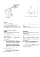
R-351NW Control panel frame Display window Small backing paper Rubber connector Screws LED sheet LCD holder Liquid Control unit crystal display Panel sub assembly Control panel frame Small depression Large depression Membrame switch Graphic sheet Figure C-2a Graphic Sheet and Membrane Switch Replacement Slit Ribbon cable of membrane switch Figure C-2b Ribbon Cable of Membrane Switch [9] TURNTABLE MOTOR REMOVAL 1. REMOVAL 1. Disconnect the power supply cord. 2. Remove turntable and turntable support from oven cavity. 3. Lay the oven on it's backside. Remove the turntable motor cover by snipping off the material in four corners. 4. Where the corners have been snipped off bend corner areas flat. No sharp edges must be evident after removal of the turntable motor cover. 5. Disconnect wire leads from turntable motor. (See "Positive lock connector removal") 6. Remove one (1) screw holding turntable motor to oven cavity. 7. Now, the turntable motor is free. 8. After replacement use the one (1) screw to fit the turntable motor cover. [10] COOLING FAN MOTOR REMOVAL 1. REMOVAL 1. Disconnect the power supply cord and remove outer case. 2. Open the door and block it open. 3. Discharge high voltage capacitor. 4. Disconnect the wire leads from the fan motor. 5. Remove the two (2) screws holding the fan motor to the oven cavity back plate. 6. Remove the fan blade from the fan motor shaft according to the following procedure. 7. Hold the edge of the rotor of the fan motor by using a pair of groove joint pliers. CAUTION: Make sure that no metal pieces enter the gap between the rotor and the stator of the fan motor because the rotor is easily shaven by pliers and metal pieces may be produced. Do not touch the pliers to the coil of the fan motor because the coil may be cut or injured. Do not disfigure the bracket by touching with the pliers. 8. Remove the fan blade assembly from the shaft of the fan motor by pulling and rotating the fan blade with your hand. 9. Now, the fan blade will be free. CAUTION: Do not re-use the removed fan blade because the hole (for shaft) may be larger than normal. 10. Now, the fan motor is free. 2. INSTALLATION 1. Install the fan blade to the fan motor shaft according to the following procedure. 2. Hold the center of the bracket which supports the shaft of the fan motor on the flat table. 3. Apply the screw lock tight into the hole (for shaft) of the fan blade. 4. Install the fan blade to the shaft of fan motor by pushing the fan blade with a small, light weight, ball peen hammer or rubber mallet. 5. Install the fan motor assembly to the oven cavity back plate with two (2) screws. CAUTION: Do not hit the fan blade strongly when installed because the bracket may be disfigured. Make sure that the fan blade rotates smooth after installation. Make sure that the axis of the shaft is not slanted. 6. Connect the wire leads to the magnetron and fan motor, referring to the pictorial diagram. 11 - 4
-
 1
1 -
2
-
3
-
4
-
5
-
6
-
7
-
8
-
9
-
10
-
11
-
12
-
13
-
14
-
15
-
16
-
17
-
18
-
19
-
20
-
21
-
 22
22 -
 23
23 -
 24
24 -
 25
25 -
 26
26 -
 27
27 -
 28
28 -
 29
29 -
 30
30 -
 31
31 -
 32
32 -
33
-
34
-
35
-
36
-
37
-
38
-
39
-
40
 |
 |
