Sharp LC-32LE451U Operation Manual - Page 28
Appendix - vesa
 |
View all Sharp LC-32LE451U manuals
Add to My Manuals
Save this manual to your list of manuals |
Page 28 highlights
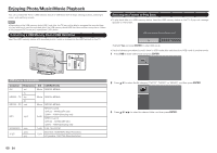
Appendix Wall Mount Kit Specifications Standard dimensions for wall mount kits are shown below. • The illustration is based on the LC-48LE551U model as an example. WALL a1 a2 WALL MOUNT KIT Model Item LC-32LE551U LC-32LE451U LC-39LE551U Wallmount Footprint 100mm x 100mm 100mm x 100mm 100mm x 100mm v The mounting means should be strong enough to bear the weight of the display. v The wall mounting bracket should have UL or related approval. LC-48LE551U 200mm x 200mm B b1 USB MHL R OPTICAL b2 b3 AUDIO OUT L AC IN COMPONENT / VIDEO DTV / TV 1 2 Y/V Pb/Cb Pr/Cr L AUDIO R CABLE / ANTENNA A c1 WALL MOUNT KIT WALL MOUNT UNIT SCREW CABINET Do not install the wall mount kit while your TV is turned on. It may result in personal injury due to electric shock. MOUNTING HOLES DEPTH OF MOUNTING HOLES For the screws, refer to the table shown below. Item Standard Screws Length(Depth of mounting holes) Quantity LC-32LE551U M4 (Use 0.7 pitch screws) Model LC-32LE451U LC-39LE551U M4 (Use 0.7 pitch screws) M4 (Use 0.7 pitch screws) 15/32 (12mm) 4pcs LC-48LE551U M6 (Use 1.0 pitch screws) NOTE • Do not mount the TV at a tilt. • Do not use screws that do not comply with the VESA standard screw specifications. • Do not use screws that are longer than the standard length. Screws that are too long may cause damage to the inside of the TV. • Do not fasten the screws too firmly or loosely. This may damage the product or cause the product to fall, leading to personal injury. SHARP is not liable for these kinds of accidents. • SHARP is not liable for product damage or personal injury when a non-VESA or non-specified wall mount is used or the consumer fails to follow the product installation instructions. 27
-
 1
1 -
2
-
3
-
4
-
5
-
6
-
7
-
8
-
9
-
10
-
11
-
12
-
13
-
14
-
15
-
16
-
17
-
18
-
19
-
20
-
21
-
22
-
 23
23 -
 24
24 -
 25
25 -
 26
26 -
 27
27 -
 28
28 -
 29
29 -
 30
30 -
 31
31 -
 32
32 -
 33
33 -
34
-
35
-
36
-
37
-
38
-
39
-
40
-
41
-
42
-
43
-
44
-
45
-
46
-
47
-
48
-
49
-
50
-
51
-
52
-
53
-
54
-
55
-
56
-
57
-
58
-
59
-
60
-
61
-
62
-
63
-
64
-
65
-
66
-
67
-
68
 |
 |
