Sharp CD-XP7700 Service Manual - Page 14
Adjustment
 |
View all Sharp CD-XP7700 manuals
Add to My Manuals
Save this manual to your list of manuals |
Page 14 highlights
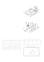
CD-XP700/CD-XP7700 CD MECHANISM SECTION Perform steps 1, 2, 3, 10, 11,12 and 13 of the disassembly method to remove the CD mechanism. How to remove the loading motor (See Fig. 14-1) 1. Bend the hooks (A1) x 6 pcs., to remove the loading motor. Loading Tray Loading Motor Loading Motor PWB (A1)x6 How to remove the pickup (See Fig. 14-2) 1. Remove the stop washer (B1) x 1 pc., to remove the gear (B2) x 1 pc. 2. Remove the screws (B3) x 2 pcs., to remove the shaft (B4) x 1 pc. 3. Remove the pickup. Note After removing the connector for the optical pickup from the connector wrap the conductive aluminium foil around the front end of connector so as to protect the optical pickup from electrostatic damage. Figure 14-1 (B3)x2 ø2.6x6mm Stop Washer (B1)x1 Pickup Shaft (B4)x1 Gear (B2)x1 CD Mechanism ADJUSTMENT Figure 14-2 MECHANISM SECTION • Driving Force Check Torque Meter Specified Value Play: TW-2111 Tape 1: Over 80 g Tape 2: Over 80 g • Torque Check Torque Meter Specified Value Play: TW-2111 Fast forward: TW-2231 Rewind: TW-2231 Tape 1 30 to 80 g.cm - - Tape 2 30 to 80 g.cm 70 to 180 g.cm 70 to 180 g.cm • Tape Speed Test Tape Normal MTT-111 speed Adjusting Point Variable Resistor in motor. Specified Instrument Value Connection 3,000 ± 30 Hz Speaker Terminal (Load resistance: 6 ohms) TAPE MECHANISM Tape Motor - 14 - Variable Resistor in motor Figure 14-3
-
 1
1 -
2
-
3
-
4
-
5
-
6
-
7
-
8
-
 9
9 -
 10
10 -
 11
11 -
 12
12 -
 13
13 -
 14
14 -
 15
15 -
 16
16 -
 17
17 -
 18
18 -
 19
19 -
20
-
21
-
22
-
23
-
24
-
25
-
26
-
27
-
28
-
29
-
30
-
31
-
32
-
33
-
34
-
35
-
36
-
37
-
38
-
39
-
40
-
41
-
42
-
43
-
44
-
45
-
46
-
47
-
48
-
49
-
50
-
51
-
52
-
53
-
54
-
55
-
56
-
57
-
58
-
59
-
60
-
61
-
62
-
63
-
64
-
65
-
66
-
67
-
68
-
69
-
70
-
71
-
72
 |
 |
