Sanyo PLV-HD2000 RS232C Expand - Page 52
CR_INFPFAIL Command
 |
UPC - 086483060502
View all Sanyo PLV-HD2000 manuals
Add to My Manuals
Save this manual to your list of manuals |
Page 52 highlights
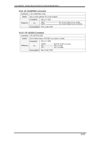
PLV-HD2000 Expand Serial Command Functional Specifications 9.10.5. CR_INFPFAIL Command Command "CR_INFPFAIL" [CR] Details Get the power failure status (Normal/Fail) at each check point. Data consists of HEX values with 48 bits. Power Failure checkpoints are 16 points in Main Unit, 8 in Sub Power Unit, 1 in Current Sensor, and 4 in Fan Sensor. For Main Unit and Sub Power Unit, each bit corresponds to their check points and indicates the status of "Normal/Abnormal" according to "HI/LO" logic. Normal ------ HI (1) Power Failure ------ LO (0) For Current sensor, the status of "Normal/Abnormal" is represented by whole 8bits of "HI/LO". Normal ------ ALL HI (FF) Power Failure ------ ALL LO (00) Acceptable "000_%1" [CR] Represents hexadecimal digit with 48 bits as a 12-digit string. 47-32 Bits (16Bits) indicates the status of Main Unit No.1-16 31-24 Bits (8Bits) indicates the status of Sub Power Unit No.1-8 23- 16 Bits (8Bits) indicates the Current sensor status 15 - 0 Bits (16Bits) indicates the Fan sensor status e.g. "000000000000" ------ power is failed at all checkpoints. "000100000000" ------ Main Unit No.1 is normal, others are failed "000200000000" ------ Main Unit No.2 is normal, others are failed Response %1 "000300000000" ------ Main Unit No.1-2 are normal, others failed "FFFE00000000" ----- Main Unit No.2-16 are normal, others failed "FFFF00000000" ----- Main Unit No.1-16 are all normal, others failed "000001000000" ----- Sub Power Unit No.1 is normal, others failed "0000FF0000" --- Sub Power Unit No.1-8 are normal, others failed "FFFFFF00FF" ------ Main Unit, Sub Power Unit, and Fan sensor are all normal, Current sensor is failed "000000FF0000" -------- Current sensor is normal, others failed "FFFFFFFFFFFF" ------ All power is normal Unacceptable "Error Code" [CR] 52/56
-
 1
1 -
2
-
3
-
4
-
5
-
6
-
7
-
8
-
9
-
10
-
11
-
12
-
13
-
14
-
15
-
16
-
17
-
18
-
19
-
20
-
21
-
22
-
23
-
24
-
25
-
26
-
27
-
28
-
29
-
30
-
31
-
32
-
33
-
34
-
35
-
36
-
37
-
38
-
39
-
40
-
41
-
42
-
43
-
44
-
45
-
46
-
 47
47 -
 48
48 -
 49
49 -
 50
50 -
 51
51 -
 52
52 -
 53
53 -
 54
54 -
 55
55 -
 56
56
 |
 |
