Sanyo PLCXF60 Instruction Manual, PLC-XF60 - Page 38
Input 3, Y, Pb/Cb, Pr/Cr, Video, RGB PC Digital, RGB AV HDCP
 |
View all Sanyo PLCXF60 manuals
Add to My Manuals
Save this manual to your list of manuals |
Page 38 highlights
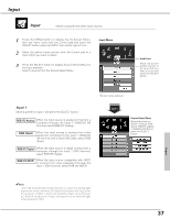
Input Input 2 Move a pointer to Input 2 and press the SELECT button. RGB Video When the input source is analog coming from a computer through the Input 2 (5 BNC-type: Red, Green, Blue, H. Sync. and V. Sync.) terminal, select RGB. When video input signal is connected to the Input 2 (VIDEO) terminal , select Video. Y, Pb/Cb, Pr/Cr When the input source is component coming from video equipment connected to the Input 2 (Y, Pb/Cb, Pr/Cr) terminal, select Y, Pb/Cb, Pr/Cr. Input 3 Move a pointer to Input 3 and press the SELECT button. Video When video input signal is connected to the Input 3 (VIDEO) terminal, select Video. Y, Pb/Cb, Pr/Cr When the input source is component coming from video equipment connected to the Input 3 (Y, Pb/Cb, Pr/Cr) terminal, select Y, Pb/Cb, Pr/Cr. S-Video When video input signal is connected to the Input 3 (S-VIDEO) terminal, select S-Video. Input 4 When digital PC/AV source is connected to the Warp & Blending board inserted into the Input 4 terminal, the following source menu will be displayed. RGB (PC Digital) When the input source is digital coming from a computer through the Input 4 (DVI) terminal, select RGB (PC Digital) RGB (AV HDCP) When the input source compatible with HDCP is coming from video equipment through the Input 4 (DVI) terminal, select RGB (AV HDCP). ✔Note: Warp & Blending board is initially installed into the Input 4 terminal slot. For details on Warp & Blending feature, refer to the enclosed operation manual. Input 5 A source menu appears corresponding to the board module inserted into the Input 5 terminal. Source Select Menu Move the pointer to RGB, Video or Y, Pb/Cb, Pr/Cr and press the SELECT button. Source Select Menu Move the pointer to Video, Y, Pb/Cb, Pr/Cr or S-Video and press the SELECT button. ✔Note: • Input 4 and Input 5 can not be selected when no interface board is inserted into the respective slots. (p21) • Input 5 terminal can only accept digital signals. • Adjusted values or selected settings in Input 4 and Input 5 return to factory default setting when the connected interface boards are removed from those terminal slots. 38
-
 1
1 -
2
-
3
-
4
-
5
-
6
-
7
-
8
-
9
-
10
-
11
-
12
-
13
-
14
-
15
-
16
-
17
-
18
-
19
-
20
-
21
-
22
-
23
-
24
-
25
-
26
-
27
-
28
-
29
-
30
-
31
-
32
-
 33
33 -
 34
34 -
 35
35 -
 36
36 -
 37
37 -
 38
38 -
 39
39 -
 40
40 -
 41
41 -
 42
42 -
 43
43 -
44
-
45
-
46
-
47
-
48
-
49
-
50
-
51
-
52
-
53
-
54
-
55
-
56
-
57
-
58
-
59
-
60
-
61
-
62
-
63
-
64
-
65
-
66
-
67
-
68
-
69
-
70
-
71
-
72
-
73
-
74
-
75
-
76
-
77
-
78
-
79
-
80
-
81
-
82
-
83
-
84
 |
 |
