Sanyo PLC-XU88 User Manual - Page 10
Rear Terminal, COMPUTER/COMPONENT AUDIO - manual
 |
View all Sanyo PLC-XU88 manuals
Add to My Manuals
Save this manual to your list of manuals |
Page 10 highlights
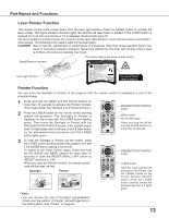
Rear Terminal ① ② ③ Part Names and Functions ④ ⑫ ⑪ ⑩⑨ ① USB In order to operate the computer with the remote control and use the PAGE ▲▼buttons on the remote control during a presentation, connect the USB port of the computer to the USB terminal with a USB cable (not supplied) (pp.12, 18). ② SERVICE PORT This jack is used to service the projector. ③ COMPUTER IN 1/DVI-I Connect computer output (Digital/Analog DVI-I type) to this terminal (p.18). ④ COMPUTER IN 2/COMPONENT IN/ MONITOR OUT This terminal is switchable and can be used for input from a computer or output the incoming RGB analog signal from COMPUTER IN1 terminal to the other monitor. Set the terminal up as either Computer input or Monitor output properly. (Used for Monitor out, this terminal outputs only incoming signal from COMPUTER IN 1 terminal.) (pp18,20) ⑤ S-VIDEO IN Connect the S-VIDEO output signal from video equipment to this jack (p.19). ⑥ AUDIO IN Connect the audio output signal from video equipment connected to ⑤ or ⑫ to this jack. For a mono audio signal (a single audio jack), connect it to the L (MONO) jack (p.19). ⑦ AUDIO OUT (VARIABLE) Connect an external audio amplifier to this jack (pp.18-20). This terminal outputs sound from AUDIO IN terminal (⑥ or ⑪). ⑧ LAN Connection Terminal Connect the LAN cable (refer to the owner's manual "Network Set-up and Operation"). ⑨ SD Card Slot Insert the SD card memory (not supplied) for Memory viewer operation(refer to the owner's manual of Memory viewer). ⑩ SD Card Indicator Display the status of SD card. When inserting SD Card, the indicator lights, and when unplugging SD Card, the indicator turns off. ⑪ COMPUTER/COMPONENT AUDIO IN Connect the audio output (stereo) signal from a computer or video equipment connected to ③ or ④ to this jack (pp.18, 20). ⑫ VIDEO IN Connect the composite video output signal to this jack (p.19). 10
-
 1
1 -
2
-
3
-
4
-
 5
5 -
 6
6 -
 7
7 -
 8
8 -
 9
9 -
 10
10 -
 11
11 -
 12
12 -
 13
13 -
 14
14 -
 15
15 -
16
-
17
-
18
-
19
-
20
-
21
-
22
-
23
-
24
-
25
-
26
-
27
-
28
-
29
-
30
-
31
-
32
-
33
-
34
-
35
-
36
-
37
-
38
-
39
-
40
-
41
-
42
-
43
-
44
-
45
-
46
-
47
-
48
-
49
-
50
-
51
-
52
-
53
-
54
-
55
-
56
-
57
-
58
-
59
-
60
-
61
-
62
-
63
-
64
-
65
-
66
-
67
-
68
-
69
-
70
-
71
-
72
-
73
-
74
-
75
-
76
-
77
 |
 |
