Rane SM82S Operation Manual - Page 5
Front Panel Description - manual
 |
View all Rane SM82S manuals
Add to My Manuals
Save this manual to your list of manuals |
Page 5 highlights
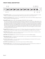
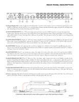
FRONT PANEL DESCRIPTION 32 7 6 10 9 1 2 3 4 5 6 7 8 10 L OL 10 L 4 6 OL 10 L 4 6 OL 10 L 4 6 OL 10 L 4 6 OL 10 L 4 6 OL 10 L 4 6 OL 10 L 4 6 OL 4 6 5 C 5 C 5 C 5 C 5 C 5 C 5 C 5 C 2 8 2 8 2 8 2 8 2 8 2 8 2 8 2 8 0 R SEND PAN 0 10 LEVEL 0 R SEND PAN 0 10 LEVEL 0 R SEND PAN 0 10 LEVEL 0 R SEND PAN 0 10 LEVEL 0 R SEND PAN 0 10 LEVEL 0 R SEND PAN 0 10 LEVEL 0 R SEND PAN 0 10 LEVEL 0 R SEND PAN 0 10 LEVEL RETURN L 4 C 2 OL 6 8 R PAN 0 10 LEVEL OUTPUT L 4 C 2 OL 6 8 R PAN 0 10 LEVEL SM82S STEREO MIXER POWER 41 5 8 11 1 Input LEVEL controls: are rotary stereo attenuators that adjust the amount of both Left and Right signals applied to an Input. Outputs are summed for mixing with all other Inputs. The unity gain position of this control is located at "7.5." 2 Input OverLoad indicators: glow red whenever its corresponding Input's output exceeds a level 4 dB below clipping, letting you know it's a good idea to turn this Input down a bit. 3 Input PAN controls: operate as 'PAN' with a mono signal, and 'BALANCE' with a stereo signal. PAN: When a mono input is used (no plug in the RIGHT Input jack), the signal 'moves' from the Left to Right channels. At the "L" extreme top of travel the sound source is heard from the Left output; at the other "R" extreme bottom it is heard only from the Right output. In the middle, the sound is heard equally from each output, but is reduced in level by 3 dB relative to its original value. This guarantees that as the sound is panned from one side to the other, it maintains equal loudness (power) for all positions. BALANCE: In its center detent, Left and Right signals to each channel are allowed to pass at their original relative levels, therefore preserving the stereo image from devices connected to both of the Inputs. When the control is moved vertically toward the "L" position, the Right channel level is decreased while the Left channel level is maintained. The opposite occurs if the control is moved from the detent down toward the "R". 4 Input SEND Level controls: determine the amount of Post-Fade stereo Input is fed to the Loop Send buses. Each Input's stereo SEND is summed on this bus and is available at the respective LEFT and RIGHT LOOP SENDS on the rear of the mixer. 5 RETURN LEVEL control: is a rotary stereo attenuator that controls the amount of Return which is to be added to the Main Output. The unity gain position of this control is located at "7.5." 6 RETURN OverLoad indicator: glows red whenever the return levels exceed a level of 4 dB below clipping. 7 RETURN PAN control: is a vertical slider that controls the effect or source connected to the LOOP RETURN in the same way the Input PAN controls work (see 3 above). 8 OUTPUT LEVEL control: is a rotary stereo attenuator that controls the final signal Level at the main OUTPUT jacks. The unity gain position of this control is located at "7.5". 9 OUTPUT OverLoad indicator: glows red any time the output level exceeds 4 dB below clipping. q OUTPUT PAN control: is a vertical slider that operates in the same fashion as the PAN control described in item 3 above. It however, determines the relative levels of the LEFT and RIGHT MAIN OUTPUTS only. Manual-2
-
 1
1 -
 2
2 -
 3
3 -
 4
4 -
 5
5 -
 6
6 -
 7
7
 |
 |
