Rane MT4 MA 4 Amplifier Manual - Page 6
Individual FAULT FLAG ports, MASTER, or SLAVE, operation, automatic redundancy switching,
 |
View all Rane MT4 manuals
Add to My Manuals
Save this manual to your list of manuals |
Page 6 highlights
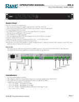
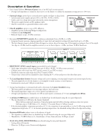
• ºIndWivhiednuaalfFauAlUt iLsTdMRAAeFNDtEELeCIcNAOtRUeGP.d.S.Apo. onrptMsowaAree4rpurpo,vitdheedchfoarnenaecClhOoMErcQMUhEcIRaPhCMnIaAEnnLNTeAnUl2e.D4lITsOJ affected are not enaOCblUalsesTd2P,WUairniTndgSthe appropriate front panel fault indicators are lit. A detected fault is re-tested every 104seINcTonEdXTs. 3 INT EXT INT EXT INT EXT 2 1 º When a channel develops a fault while operatiAnCNg,00t1he chaR nnel shuLtOsADdown andLOAthDe outpuLtOrAeDlay is turLnOAeDd OFF. A detected fault is re-tested every 10 seconds.345 482 º Possible faults include: supply under-voltage, over-voltage, voltage imbalance, output short to ground, output º short to supply, output Channels set to Master, sho1r0t0t-2o40oV utput, clock not running, FOR CONTINUED GROUNDING PROTECTION DO NOT REMOVE over d5r0i/v6e0 Htzh5e00fWaAuTlTtS flaTgHIShSiCgRhEWw. hen no fault is s+afe- te+mp-er+atu-re.+ - + present. Passive pull down -+ pulls -+ the -+- fault flag low when a fault occurs or power is lost. Slave channels read the status of the fault flag (see Master/Slave below). º The fault flag uses 5 volt logic with high-side active drive and passive pull down. No fault = +5V. Fault = 0V. FAULT FLAG Active Low 4321 4321 MODE HIGH-PASS 20Hz 40Hz 60Hz 80Hz MASTER C SLAVE ON ON 1234 12 1 2 3 4 EXP O • Each channel is set for MASTER (up) or SLAVE (down) operation using the rear panel dipswitch. º Master channels write fault flag status. º Slave channels read fault flag status. º The Master setting is used for remote fault reporting and/or automatic redundancy switching control. º The Slave setting is used for individual channel remote power sequencing or automatic redundancy switching. • Internal automatic redundancy switching is provided (see page Manual-4). º The primary amplifier channel is seMRtAANtDoEE CIMNORUPa..Ss.At.er. TMhAe b4ackup amplifierCOcMEhQMaUEnIRPCnMIAEeLNlTAiU2sD4ITOJ OUTPUTS Class 2 Wiring set to Slave. The Master fault flag is wired to the Slave fault flag. If two different INT EXT INT EXT 4 3 INT EXT INT EXT 2 1 MA 4 amplifiers are involved (recommended), also wire the fault flag grounR ds LOAD LOAD LOAD LOAD ACN 001 together. Drive Master and Slave audio inputs from the same sou3r4c5e4,82and set the SENSITIVITY controls the same. Master and Slave front panel power switches must be ON. 100-240V FOR CONTINUED GROUNDING PROTECTION DO NOT REMOVE º When a fault is detected on a Master amplifi5e0r/6c0hHaz n50n0eWlA,TTtShatTHcIhS SaCnRnEWe.l is shut down, the output relay is switched to off, internally connecting the load to the EXTernal amplifier input. The front panel fault indicator is then lit. º The Slave channel remains in low-power standby (Ready indicator flashing) until a fault is detected (fault flag no longer driven high by the Master channel). When a fault is detected, the Slave channel performs a self test, switches to run mode, and closes the output relay (takes about 500 ms). The output of the Slave channel is connected to the EXTernal amplifier input on the Master channel. FAU FLA Active 432 432 • Comprehensive front panel metering is included for each channel: º Headroom meters are four-segment. The peak signal level is compared to the limit threshold and the difference in dB is displayed as remaining headroom. The limiter threshold is adjusted to account for the average load impedance, resulting in load compensated headroom indication. º Red Limiter, yellow Compressor and yellow Expander indicators light when the associated dynamics control is active. º A red Fault indicator lights when a fault is detected º The green Load indicator is off when impedance is above 16 Ω, on when impedance is between 2 and 16 Ω and flashing when the impedance is below 2 Ω. º The green Ready indicator is off when the power switch is off, flashing when the power switch is on and the unit is in standby (Slave channel with high fault flag) and on when the channel is active. 1 3 Limit 6 Comp 12 Exp 24 dB Headroom 2 Fault Load Ready 3 Limit 6 Comp 12 Exp 24 dB Headroom 3 Fault Load Ready 3 Limit 6 Comp 12 Exp 24 dB Headroom 4 Fault Load Ready 3 Limit 6 Comp 12 Exp 24 dB Headroom Fault Load Ready ON Manual-3
-
 1
1 -
 2
2 -
 3
3 -
 4
4 -
 5
5 -
 6
6 -
 7
7
 |
 |
