Rane MT4 MA 4 Amplifier Manual - Page 5
Description & Operation
 |
View all Rane MT4 manuals
Add to My Manuals
Save this manual to your list of manuals |
Page 5 highlights
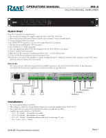
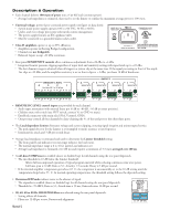
Description & Operation • Each channel delivers 100 watts of power into a 4 or 8Ω load (constant power). º Average load impedance is estimated, then used to set the limiter to confine the maximum average power to 100 watts. • Universal voltage, power-factor-corrected power supply (see figure on data sheet). º Switch-mode power supply operates 100 to 240 VAC, 50 Hz or 60 Hz. º Under- and over-voltage protection with inrush current management. º The power supply features an IEC appliance inlet. º Must be connected to a grounded mains socket-outlet. • Class D amplifiers operate at up to 85% efficiency. º Amplifiers operate in floating Bridged configuration. º Channels are not bridgeable. º Balanced Inputs accept +22 dBu maximum. MADE IN U.S.A. RANE CORP. MA 4 COMMERCIAL AUDIO EQUIPMENT 24TJ R 100-240V 50/60 Hz 500 WATTS FOR CONTINUED GROUNDING PROTECTION DO NOT REMOVE THIS SCREW. INT E 4 LOAD +-+ +-+ • Rear panel SENSITIVITY controls allow continuous adjustment from +22 dBu to +4 dBu. º Integrated Limiter prevents clipping regardless of input level and sensitivity setting with input levels up to +22 dBu. º The best dynamic range is achieved when all stages in a system clip at the same time. If the signal processing in front of the amplifier clips at +22 dBu, and the amplifier sensitivity is set so that it clips at + 4 dBu, you loose 18 dB of headroom. FAULT FLAG Active Low 321 321 MODE HIGH-PASS 20Hz 40Hz 60Hz 80Hz MASTER COMP SLAVE ON ON ON 1234 1234 1 2 3 4 EXP ON 4 Vr Vc REMOTE LEVEL 3 2 1 Use Rane VR 2 or 20 kΩ pot Vr Vc Vr Vc Vr Vc Vr Vc Vr Vc Vr Vc Vr Vc INPUTS 4 SENSITIVITY 13 +- 3 SENSITIVITY 13 +- 2 SENSITIVITY 13 +- 1 SENSITIVITY 13 +- +- 22 4 dBu +- 22 4 dBu +- 22 4 dBu +- 22 4 dBu • REMOTE DC LEVEL control inputs are provided for each channel. º Audio taper attenuation with external linear pot (0 dB to -80 dB, -16 dB at center position). º Clickless mute with switch (use SPST switch; connect Vc to GND to mute). º Euroblock connector with strain relief (Vref, Vcontrol, GND). º One pot may control all four channels by daisy-chaining the Vc of the used port to the other three ports. • The Load-dependent Limiter eliminates voltage and current clipping, ensuring signal integrity and uninterrupted service. º The peak signal detector for the Limiter is oversampled to insure accuracy at any frequency. º Instantaneous attack and 3 dB per second decay. • Average load impedance is estimated and used to determine the Limiter threshold setting. º The front panel Load indicator (see metering) indicates the load status. º The normal impedance range is 2 to 16 Ω. (green Load indicator on). º Average load impedance is estimated over 180 ms and requires a minimum of 3.3 watts averaged over 180 ms. • A soft-knee COMPressor is enabled (down) or disabled (up) for all channels using the rear panel dipswitch. º The rms threshold is 10 dB below the Limiter threshold. · Allows full uncompressed operation of typical program material while reducing continuous sine wave power. · Soft knee span is 10 dB; Ratio is 3:1; Attack is 1.5 seconds; Decay is 3 dB per second. º If the internal amplifier temperature goes above 65˚ C, the compressor is automatically set to the 10 dB setting until the temperature drops below 55˚ C. At normal operating temperatures, the threshold setting follows the dipswitch setting. MRAANDEE•CINOºRUDP..So.TA.whneweMxaAprda4nEdXerPiasnednearblreeddu(CdcOeoMEswQMUEnnIRPoC)MIiAEosLNerTAUid2nD4iITsOJtahbeleadbs(eunpc)efoorf signaOl.UTPUTS all chCalnasns e2lWs iurinsging the rear panel dipswitch. º Threshold is -70 dBFS; Ratio is 3:1; Atta4ckINtTimEXeTis 350INmT sE; XGT ain2reINdTucEtXiTon 110INdTBEpXTer second. FAULT FLAG R ACN 001 LOAD LOAD LOAD LOAD Active Low • 20, 40, 60 or 80 Hz HI3G45H482-PASS filters ar+e s-ele+cte-d u+sin-g +the- rea+r p-ane+l d-ip+swi-tch+. - 4321 º Setting affects all channels. º Filt1e0r0s-2a40rVe 50/60 Hz 500 W1A2TTSdBFPTOHRpROISeTCrESOCCNoTRTIEcOIWNNt.UaDEvODeNG,ORBTOURuNEtMDtIOeNVrGEworth+ali-gn+me-nt.+ - + - +-+-+-+- 4321 Manual-2 MODE HIGH-PASS 20Hz 40Hz 60Hz 80Hz MASTER COMP SLAVE ON ON ON 1234 1234 1 2 3 4 EXP ON 4 Vr Vc REMOTE 3 Use Rane VR Vr Vc Vr Vc Vr Vc
-
 1
1 -
 2
2 -
 3
3 -
 4
4 -
 5
5 -
 6
6 -
 7
7
 |
 |
