Pyle PLTM40 User Manual - Page 13
Pyle PLTM40 Manual
 |
View all Pyle PLTM40 manuals
Add to My Manuals
Save this manual to your list of manuals |
Page 13 highlights
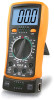
4.6.1 Connect the black test lead to the COM jack and the red test lead to the V/ 0 jack. 4.6.2 Set the transform switch at the V range Q position. 4.6.3 Connect test leads across the source or load under measurement. 4.6.4 You can get reading from LCD. NOTE: • At the low voltage range, the meter will show unsteady reading when test leads E VA haven't touched the circuit, it's normal because the meter is very sensitive. When test leads touch the circuit, you can get the true reading. • When only the figure "1" is displayed it indicates Overrange situation and higher range has to be selected • When the value scale to be measured is unknown beforehand set the range selector at the highest position 4.7 MEASURING DC CURRENT A WARNING Shut down the power of the tested circuit, then connect the meter with the circuit for measurement. 1.000 1.00 O® a O 10
-
 1
1 -
2
-
3
-
4
-
5
-
6
-
7
-
 8
8 -
 9
9 -
 10
10 -
 11
11 -
 12
12 -
 13
13 -
 14
14 -
 15
15 -
 16
16 -
 17
17 -
 18
18 -
19
-
20
 |
 |
