Panasonic WU-144MF1U9E 3-Way Service Manual - Page 115
Sensor Temperature Display Function, displayed regardless of whether unit is, operating or stopped
 |
View all Panasonic WU-144MF1U9E manuals
Add to My Manuals
Save this manual to your list of manuals |
Page 115 highlights
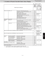
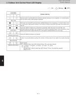
3. Remote Controller Servicing Functions 3-WAY VRF SYSTEM Remote Controller Functions ■ Sensor Temperature Display Function (displayed regardless of whether unit is operating or stopped) The procedure below displays the sensor temperatures from the remote controller, indoor unit, and outdoor unit on the remote controller. ➀ Press and hold the and buttons simultaneously for 4 seconds or longer. ➁ The unit No. "X-X" (main unit No.), item code "XX" (sensor address), and servicing monitor " " (sensor temperature) are displayed on the remote controller LCD display. (See Fig. 4-4 at right.) ➂ Press the temperature setting / buttons and select the item code to the address of the sensor to monitor. (For the relationships between the sensor addresses and sensor types, refer to the table of temperature sensors and addresses on the next page.) ➃ If group control is in effect, press the button to select the unit to monitor. Press the temperature setting buttons to select the item code to change. ➄ Press the button to return to normal remote controller display. 2 3 51 CZ-RTC2 4 * Display shows a discharge temperature of 00XX at unit No. 1-1. In case, for example, the display shows "0185" in the figure above, a discharge temperature from the outdoor unit stands for 185°F. Fig. 4-4 NOTE 4 The temperature display appears as "- - - -" for units that are not connected. * If monitor mode is engaged while normal operation is in progress, only the parts of the LCD display shown in the figure will change. Other parts continue to display the same information as during normal operation. 4 - 17
-
 1
1 -
2
-
3
-
4
-
5
-
6
-
7
-
8
-
9
-
10
-
11
-
12
-
13
-
14
-
15
-
16
-
17
-
18
-
19
-
20
-
21
-
22
-
23
-
24
-
25
-
26
-
27
-
28
-
29
-
30
-
31
-
32
-
33
-
34
-
35
-
36
-
37
-
38
-
39
-
40
-
41
-
42
-
43
-
44
-
45
-
46
-
47
-
48
-
49
-
50
-
51
-
52
-
53
-
54
-
55
-
56
-
57
-
58
-
59
-
60
-
61
-
62
-
63
-
64
-
65
-
66
-
67
-
68
-
69
-
70
-
71
-
72
-
73
-
74
-
75
-
76
-
77
-
78
-
79
-
80
-
81
-
82
-
83
-
84
-
85
-
86
-
87
-
88
-
89
-
90
-
91
-
92
-
93
-
94
-
95
-
96
-
97
-
98
-
99
-
100
-
101
-
102
-
103
-
104
-
105
-
106
-
107
-
108
-
109
-
 110
110 -
 111
111 -
 112
112 -
 113
113 -
 114
114 -
 115
115 -
 116
116 -
 117
117 -
 118
118 -
 119
119 -
 120
120 -
121
-
122
-
123
-
124
-
125
-
126
-
127
-
128
-
129
-
130
-
131
-
132
-
133
-
134
-
135
-
136
-
137
-
138
-
139
-
140
-
141
-
142
-
143
-
144
-
145
-
146
-
147
-
148
 |
 |
