Panasonic AW-IF400 System Camera and Switcher Product Lineup Catalog - Page 62
approach many high-end switchers.
 |
View all Panasonic AW-IF400 manuals
Add to My Manuals
Save this manual to your list of manuals |
Page 62 highlights
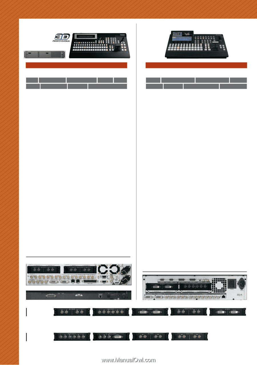
Live Switcher Control Panel Mainframe Multi-Format Live Switcher AV-HS450 1 ME Max. 20 Inputs*1 Max. 10 Outputs*2 1 Keyer 2 DSK 2 P-in-P 2ch MultiViewer 4 Aux Buses Redundant Power Supply This high-performance switcher handles the switching needs of broadcast studios, OB vans and multi-camera systems anywhere. •16 SDI inputs, four SDI outputs and two DVI-D outputs. •Luminance and chroma keying, two DSK channels, two P-in-P buses and two DVE channels. •Supports a variety of HD/SD formats, including 1080/24PsF,*3 as standard. •A wide range of optional boards also allows the input and output of analog component and various other signals. (For details, see the list of optional boards below.) •Equipped with an SD/HD up-converter function for four standard inputs, and a dot by dot function for 16 standard inputs. •A video processing function with color correction is also provided for eight inputs. •Aux 1 bus equipped with Mix transition function. •Panel layout offers direct control of functions with 16 crosspoint buttons and pattern select buttons. •Six user buttons. •Mounting the optional AV-HS04M7D 3D SDI Output Board provides 3D compatibility. Switch up to Nine 3D Image Inputs. Rear Panel Mainframe Live Switcher AV-HS410 1 ME 1 DSK Max. 13 Inputs*1 Max. 10 Outputs*2 1 Keyer 2 P-in-P 1ch MultiViewer 4 Aux Buses This compact, integrated unit includes levels of performance and function that approach many high-end switchers. •Eight SDI inputs, one DVI-D input, five SDI outputs and one DVI-D output. •Supports a variety of HD/SD formats, including 1080/24PsF, as standard. •A wide range of optional boards also allows the input and output of analog component and various other signals. (For details, see the list of optional boards below.) •Equipped with an SD/HD up-converter function for four standard inputs, and a dot by dot function for eight inputs. •A video processing function with brightness, pedestal level, saturation, and color phase correction is also provided for eight inputs. •The Memory Preview function lets you preview shot memory and event memory content. It allows image effects to be easily confirmed while on-air with this 1 M/E switcher. •Two inputs for still (STILL) and moving (CLIP) images can be saved in Video Memory, and selected as bus footage. •A 178 mm (seven inches) color LCD monitor with WVGA (800 x 480) resolution is built into the control panel. It can be switched to a wide variety of display modes, including setting menus, image monitoring and waveform/vectorscope. •12 crosspoint buttons in each A bus and B bus (for a maximum of 22 with the Shift function) provide direct control. Also comes with eight user buttons. •Plug-ins allow flexible expansion of softwarebased functions. Rear Panel Control Panel Input Option Boards AV-HS04M1 SDI Input Board SDI (HD/SD) x 2 (BNC) (Built-in Up-converter) AV-HS04M2 AV-HS04M3 Analog Component Input Board DVI Input Board HD/SD Analog Component x 2 (Y/PB/PR) DVI-I x 2 (Built-in Scaler) (Built-in Up-converter) AV-HS04M6 AV-HS04M8 Analog Composite Input Board Full HD DVI Input Board Analog Composite x 2 (Built-in Up-converter) DVI-D x 2 (compatible with WUXGA) Output Option Boards AV-HS04M4 AV-HS04M5 AV-HS04M7 62 Analog Output Board DVI/Analog Output Board SDI Output Board AV-HS04M7D 3D SDI Output Board HD/SD Analog Component x 2 (Y/PB/PR) DVI-I x 1, HD/SD Analog Component x 1(Y/PB/PR) SDI (HD/SD) x 2 (Each one has 2 outputs) (BNC) (Built-in Down-converter) SDI (HD/SD) x 2 (Each one has 2 outputs) (BNC) (Built-in Down-converter)
-
 1
1 -
2
-
3
-
4
-
5
-
6
-
7
-
8
-
9
-
10
-
11
-
12
-
13
-
14
-
15
-
16
-
17
-
18
-
19
-
20
-
21
-
22
-
23
-
24
-
25
-
26
-
27
-
28
-
29
-
30
-
31
-
32
-
33
-
34
-
35
-
36
-
37
-
38
-
39
-
40
-
41
-
42
-
43
-
44
-
45
-
46
-
47
-
48
-
49
-
50
-
51
-
52
-
53
-
54
-
55
-
56
-
 57
57 -
 58
58 -
 59
59 -
 60
60 -
 61
61 -
 62
62 -
 63
63 -
 64
64 -
 65
65 -
 66
66 -
 67
67 -
68
-
69
-
70
-
71
-
72
-
73
-
74
-
75
-
76
-
77
-
78
 |
 |