Panasonic AW-IF400 System Camera and Switcher Product Lineup Catalog - Page 43
Pin Configuration, Rear View
 |
View all Panasonic AW-IF400 manuals
Add to My Manuals
Save this manual to your list of manuals |
Page 43 highlights
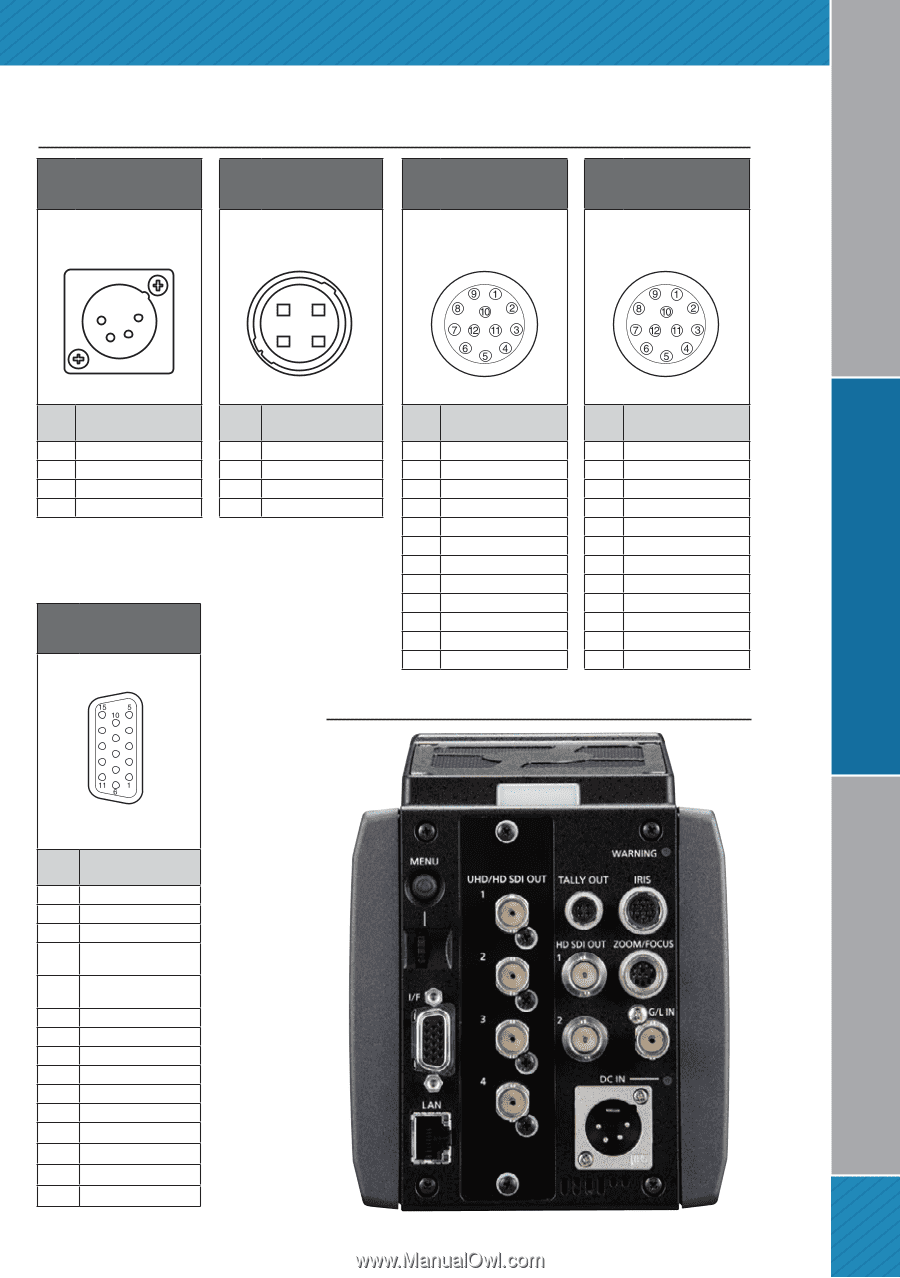
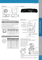
Studio Camera System Pin Configuration DC IN connector Tally output connector The R tally and G tally signals are output from this connector. As of April, 2017 IRIS connector Used to connect the IRIS control cables of the lens. Zoom/focus connector Used to connect the Zoom/focus control cables of the lens. 1 4 2 3 4 1 3 2 HA16RA-4P(77) (Hirose Electric Co.) Pin NO. Signal 1 UNREG GND 2 Not used 3 Not used 4 +12 V * Use the external power supply with correct polarity. HR10A-7R-4SC (73) (Hirose Electric Co.) Pin NO. Signal 1 GND 2 R TALLY (open collector) 3 G TALLY (open collector) 4 UNREG+12 V (max. 0.5 A) IF connector HR10A-10R-12SC (71) (Hirose Electric Co.) Pin NO. Signal 1 Return control 2 REC-START/STOP 3 GND 4 Iris manual switching 5 Iris control 6 UNREG +12 V (max. 0.75 A) 7 IRIS-POSI 8 IRIS-G-MAX 9 EXT-POSI 10 Zoom position information 11 LENS‑RXD 12 LENS‑TXD HR10A-10R-12PC (71) (Hirose Electric Co.) Pin NO. Signal 1 Focus control switching 2 Zoom control switching 3 GND 4 Not used 5 Not used 6 Not used 7 Not used 8 Focus control 9 Zoom control 10 Not used 11 COM+V voltage 12 COM-V voltage Rear View Remote Camera System Live Switcher D02-M15SAG-20L9E (Japan Aviation Electronics Industry) Pin NO. Signal 1 GND 2 Not used 3 Not used 4 TX_N (EIA422)/ TXD (EIA232) output 5 RX_N (EIA422)/ RXD (EIA232) input 6 Not used 7 G/L signal input 8 Not used 9 TX_P (EIA422) output 10 RX_P (EIA422) input 11 GND 12 Not used 13 GND 14 GND 15 GND 43
-
 1
1 -
2
-
3
-
4
-
5
-
6
-
7
-
8
-
9
-
10
-
11
-
12
-
13
-
14
-
15
-
16
-
17
-
18
-
19
-
20
-
21
-
22
-
23
-
24
-
25
-
26
-
27
-
28
-
29
-
30
-
31
-
32
-
33
-
34
-
35
-
36
-
37
-
 38
38 -
 39
39 -
 40
40 -
 41
41 -
 42
42 -
 43
43 -
 44
44 -
 45
45 -
 46
46 -
 47
47 -
 48
48 -
49
-
50
-
51
-
52
-
53
-
54
-
55
-
56
-
57
-
58
-
59
-
60
-
61
-
62
-
63
-
64
-
65
-
66
-
67
-
68
-
69
-
70
-
71
-
72
-
73
-
74
-
75
-
76
-
77
-
78
 |
 |