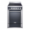
Magic Chef MCSRE24S User Manual - Page 14
Before Making The Electrical Connection, Make Sure
 |
View all Magic Chef MCSRE24S manuals
Add to My Manuals
Save this manual to your list of manuals |
Page 14 highlights
Electrical Requirements: 220-240V/50-60Hz. With recommendation to connect to a 50 Amp power supply. System Oven Light Upper Heating Element Bottom Heating Element Grill Heating Element Convection Heating Element Ventilator Motor Cooling Fan Electrical Specifications 25 W (2) 2450 W / 1960 W 1361 W 2560 W 1960 W 20 W 18 W Wattage WARNING: BEFORE MAKING THE ELECTRICAL CONNECTION, MAKE SURE THAT • The safety circuit-breaker and the electrical system are able to withstand the load of the appliance. Refer to rating label on back of range. • Rating plate is located on back of range should you need to verify any of the electrical requirements. • The power supply system has a ground connection in good working order in accordance with the regulations in force. • The electrical socket is easily accessible with the appliance installed. In all cases, the power supply lead must be positioned so that it does not reach a temperature of 122°F above the room temperature at any point. • The manufacturer is not liable for any direct or indirect damage caused by faulty installation or connection. It is therefore necessary that all installation and connection operations are carried out by qualified personnel complying with the local and general regulations in force. ELECTRICAL CONNECTION Follow these steps for the 3-wire and 4-wire installation process. 1. Remove the wire cover on the back of the range by removing the two (2) screws using a Phillips screw driver. (Refer to Figure 10.) NOTE: DO NOT discard these screws. 2. Remove the knockout ring (1-3/8") located on bracket directly below the terminal block. To remove the knockout, use a pair of pliers to bend the knockout ring away from the bracket and twist until ring is removed. (Refer to Figure 11.) 3. Assemble the strain relief in the hole. Insert the power cord through the strain relief and tighten. Allow enough slack to easily attach the cord terminals to the terminal block. If tabs are present at the end of the winged strain relief, they can be removed for better fit. (Refer to Figure 11.) Terminal Block Strain Relief 14 Figure 10 Terminal Block Cover Figure 11 Knockout Ring Bracket
-
 1
1 -
2
-
3
-
4
-
5
-
6
-
7
-
8
-
 9
9 -
 10
10 -
 11
11 -
 12
12 -
 13
13 -
 14
14 -
 15
15 -
 16
16 -
 17
17 -
 18
18 -
 19
19 -
20
-
21
-
22
-
23
-
24
-
25
-
26
-
27
-
28
-
29
-
30
-
31
-
32
-
33
-
34
-
35
-
36
-
37
-
38
-
39
-
40
-
41
-
42
-
43
-
44
-
45
-
46
-
47
-
48
-
49
-
50
-
51
-
52
 |
 |
